Supercharge Your Innovation With Domain-Expert AI Agents!

Hydraulic ball bearing

A ball bearing and hydraulic technology, which is applied in the field of elastic or flexible bearings or bearing supports, can solve problems such as ball bearing performance degradation, unusability, and ball wear, so as to reduce wear, enhance work reliability, and improve service life Effect

Active Publication Date: 2017-05-10
重庆博创知识产权运营有限公司
View PDF6 Cites 2 Cited by
  • Summary
  • Abstract
  • Description
  • Claims
  • Application Information

AI Technical Summary

Problems solved by technology

Ball bearings have a wide range of applications in the field of light industrial machinery. At the same time, in the actual use process, the ball bearing load can withstand a small shift, which makes its applicability very good. If the steel ring is in direct contact, the balls will still be worn, resulting in a decline in the performance of the ball bearing or even scrapping, making it unusable

Method used


Image

  • Hydraulic ball bearing
  • Hydraulic ball bearing
  • Hydraulic ball bearing

Examples


Embodiment 1

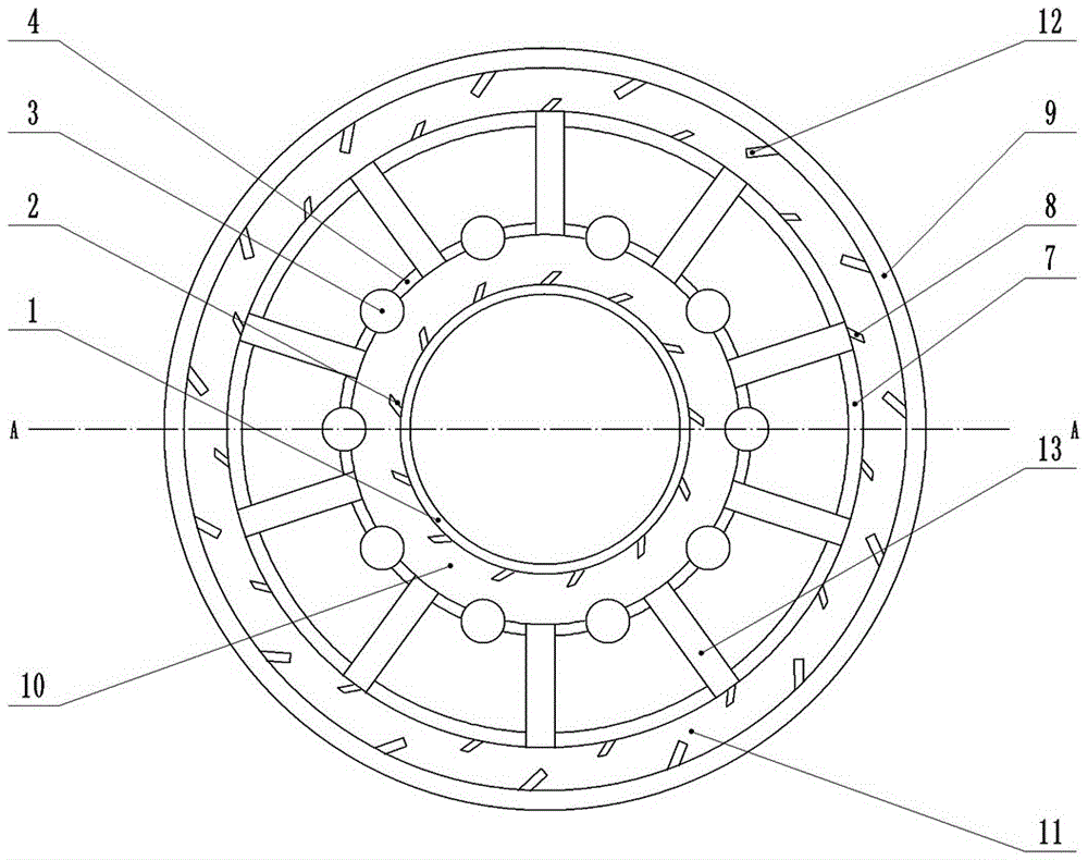
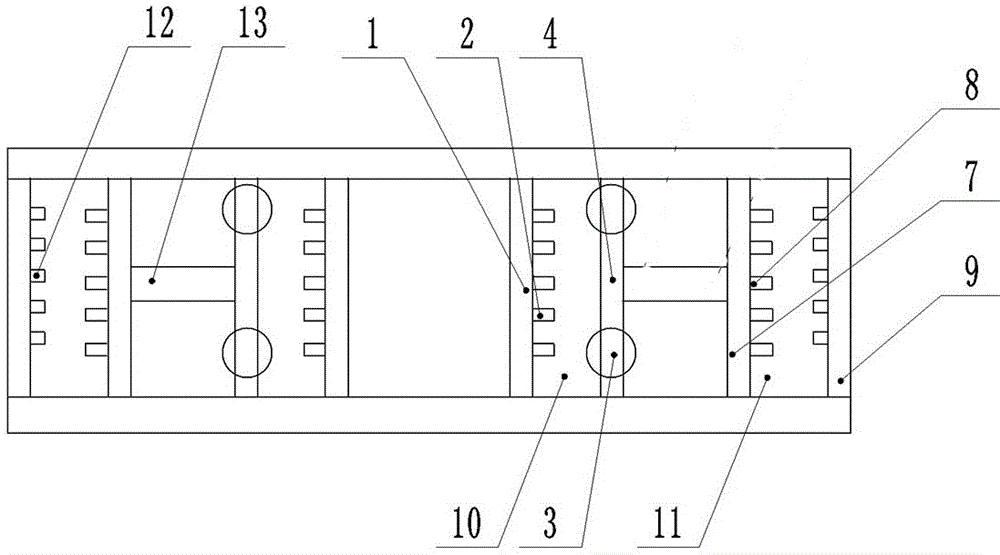
[0030] Basic as attached figure 1 and figure 2 Shown: a hydraulic ball 3 bearing, including the first steel ring 1, the second steel ring 4, the third steel ring 7 and the fourth steel ring 9 arranged in sequence from the inside to the outside, and the outer side of the first steel ring 1 is integrated The first blade 2 is formed, the second steel ring 4 is inlaid with balls 3, the balls 3 are evenly arranged on both sides of the first steel ring 1, and the first cavity is formed between the first steel ring 1 and the second steel ring 4 10. The first cavity 10 is filled with hydraulic oil, one end of the ball 3 is placed in the hydraulic oil, and the other end is located between the second steel ring 4 and the second steel ring 4 .

[0031] Both ends of the ring-shaped channel formed by the second steel ring 4 and the third steel ring 7 are clamped with closing plates, and the second steel ring 4 is connected with the side of the sealing plate in rotation, and the second st...

Embodiment 2

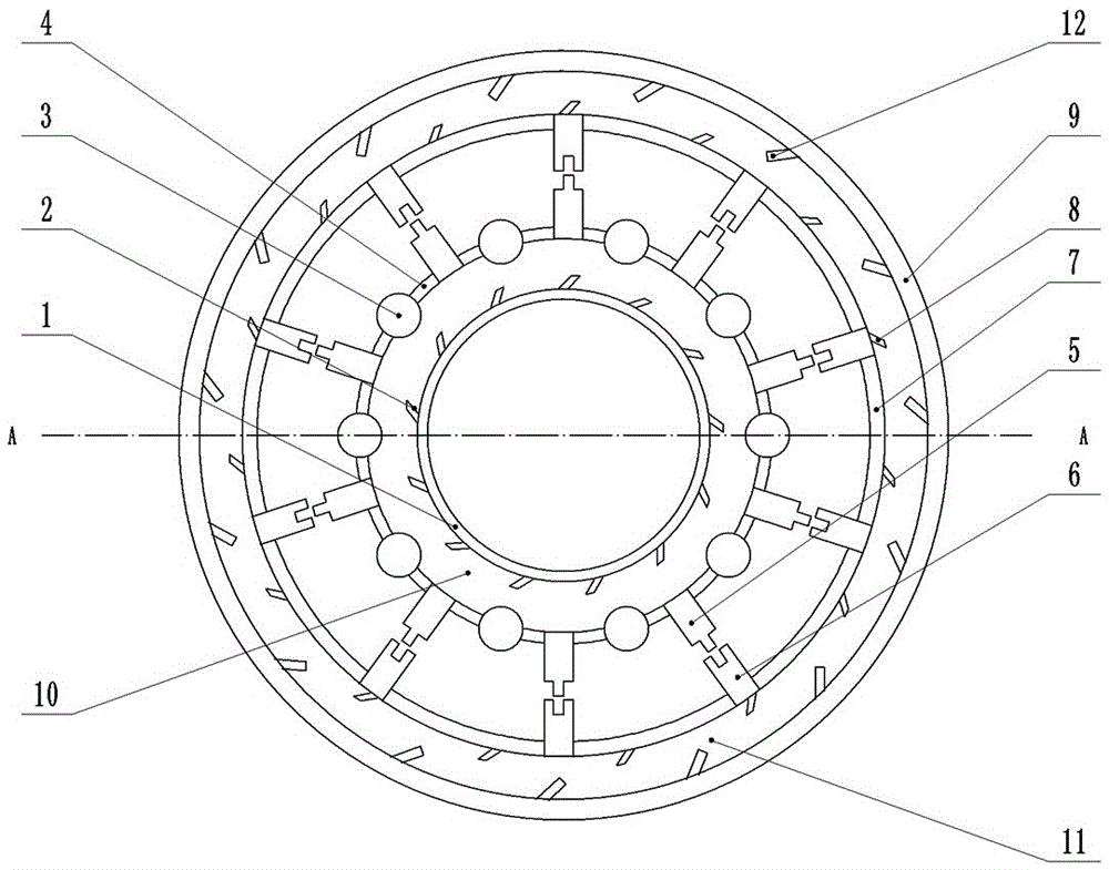
[0037] Such as image 3 and Figure 4 As shown: the difference from Example 1 is that the second steel ring 4 is integrally formed with several first cooling elements 5 in the outer circumferential direction, and the third steel ring 7 is integrally formed with the first cooling element 5 in the inner circumferential direction. There is a gap between the two cooling parts 6 , the first cooling part 5 and the second cooling part 6 that cooperate with each other.

[0038] After the workpiece has been working for a period of time, the hydraulic oil in the first cavity 10 and the second cavity 11 absorbs heat and expands, and the second steel ring 4 expands when heated, and starts to expand outward in the circumferential direction, so that the first cooling element 5 is inserted into the second The cooling element 6 further connects the second steel ring 4 and the third steel ring 7 together. When the second steel ring 4 rotates, it drives the third steel ring 7 to rotate togethe...


PUM


Abstract

The invention belongs to the technical field of elastic or flexible bearings or bearing supporting pieces special for rotation movement and particularly discloses a hydraulic ball bearing. The hydraulic ball bearing sequentially comprises a first steel ring, a second steel ring and a third steel ring from inside to outside. The face, opposite to the second steel ring, of the first steel ring is provided with first blades. The second steel ring is provided with balls. A first cavity is formed between the first steel ring and the second steel ring. The first cavity contains hydraulic oil. One end of each ball is arranged inside the hydraulic oil, and the other end of each ball is located between the second steel ring and the second steel ring. The two end faces of an annular channel formed by the second steel ring and the third steel ring are both provided with seal plates. The side, in contact with the seal plates, of the second steel ring is rotationally connected with the seal plates. Compared with the prior art, hydraulic oil has the supporting function and the drive power function at the same time, it is guaranteed that the balls cannot be worn at all, and therefore the service life of the ball is prolonged.

Description

technical field [0001] The invention belongs to the technical field of elastic or flexible bearings or bearing supports dedicated to rotary motion. Background technique [0002] Ball bearing is a kind of rolling bearing. Ball bearing mainly consists of four basic components: ball, inner steel ring, outer steel ring and retainer. During installation, the ball is generally installed in the middle of the inner steel ring and outer steel ring, and then the shaft Insert the inner steel ring to make the inner steel ring and the rotating shaft interfere with each other. When the rotating shaft rotates, the inner steel ring will be driven to rotate, and the balls will roll on the surface of the outer steel ring. The friction force in the process of power transmission will be reduced and the friction force will be improved at the same time. The transmission efficiency of mechanical power. [0003] Although the ball bearing greatly reduces the frictional force, in the known technical...

Claims


Application Information

Patent Timeline
Patent Type & Authority Applications(China)
IPC IPC(8): F16C27/04F16C37/00
CPCF16C27/045F16C37/007
Inventor 谷山品
Owner 重庆博创知识产权运营有限公司
Features
  • R&D
  • Intellectual Property
  • Life Sciences
  • Materials
  • Tech Scout
  • Unparalleled Data Quality
  • Higher Quality Content
  • 60% Fewer Hallucinations
Learn More