
Double-gear clutch device and transmission assembly

A technology of clutch device and speed ratio, applied in the direction of transmission device, gear transmission device, belt/chain/gear, etc., can solve the problems of large engine speed fluctuation, small torque output, large engine speed drop, etc., to ensure efficient operation. Performance range, meeting speed ratio requirements, and reducing the effect of speed fluctuations

Inactive Publication Date: 2017-05-10
龚小娥
View PDF6 Cites 0 Cited by
  • Summary
  • Abstract
  • Description
  • Claims
  • Application Information

AI Technical Summary

Problems solved by technology

However, it is difficult to achieve consistent speed ratio steps in the existing multi-gear design. For example, in the current 10AT variable speed drive design, the gear ratios that can be achieved in the 1st to 10th gears are 4.70, 2.99, 2.15, 1.80, and 1.52. .
It can be seen that it is difficult for the existing design to meet the requirement that the speed ratio difference between two adjacent gears is 1.2 or even smaller. When some of the gears are switched, the engine speed fluctuates greatly, and the engine may fail when upshifting. If the speed is too high, the torque output will be small, and you will feel that you can't get enough power when shifting gears, and the power will be more "meat".
In addition, the structural design of the single planetary motion mechanism is also extremely difficult to achieve a speed ratio step difference of 1.2 or less than 1.2
For example, to achieve a speed ratio output of 1.2, the input of the ring gear, the output of the planetary carrier, and the sun gear must be braked, and the speed ratio of the sun gear to the ring gear must be 5, which means that if it is in P or N gear, The engine speed is 2000RPM, so the sun gear speed is 10000RPM, and the sun gear speed is likely to be too high to cause serious consequences such as structural failure

Method used


Image

  • Double-gear clutch device and transmission assembly
  • Double-gear clutch device and transmission assembly
  • Double-gear clutch device and transmission assembly

Examples


Embodiment Construction

[0018] The following will clearly and completely describe the technical solutions of each exemplary embodiment provided by the present invention with reference to the accompanying drawings in the embodiments of the present invention. In the case of no conflict, the following embodiments and features in the embodiments can be combined with each other.

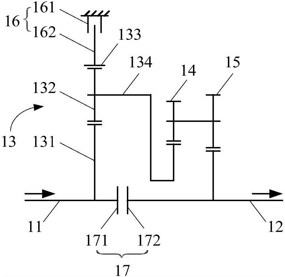
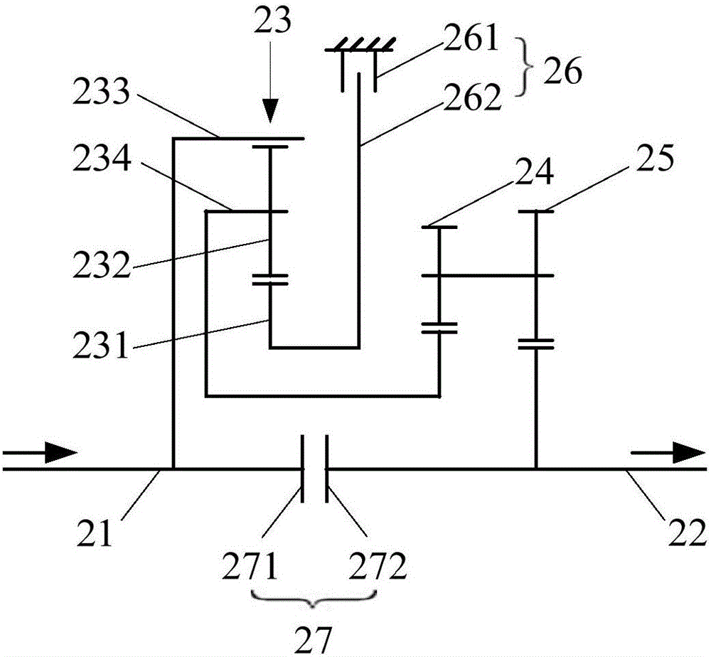
[0019] see figure 1 , is the double block clutch device of the first embodiment of the present invention. The double-speed clutch device can be connected between the output shaft of the engine and the input shaft of the transmission gear set as an independent part of the power plant, for receiving power from the engine, and passing through the transmission gear set and the final reducer connected with the transmission gear set , differential, etc. output power to drive the load. Wherein, the power device applicable to the double-speed clutch device may be a vehicle or a ship, but of course it is not limited thereto; correspond...


PUM


Abstract

The invention discloses a double-gear clutch device and a transmission assembly. The double-gear clutch device comprises a planet movement mechanism and two groups of speed ratio adjusting gears, wherein the planet movement mechanism and the two groups of speed ratio adjusting gears are connected between an input shaft and an output shaft, a mating gear of a first gear in the two groups of speed ratio adjusting gears is connected with a power output piece of the planet movement mechanism, and a mating gear of a second gear is arranged on the output shaft. According to the double-gear clutch device and the transmission assembly, a single planet row and the two groups of speed ratio adjusting gears can be utilized, so that the adjusting range of the output speed ratio can be greatly extended so as to satisfy the speed ratio requirement of transmission design, the fluctuation of engine speed of a vehicle can be reduced during gear shifting, and an engine is within the range of efficient operating performance.

Description

technical field [0001] The invention relates to the driving field, in particular to a double gear clutch device and a transmission assembly. Background technique [0002] In order to obtain better power performance, lower energy consumption, higher transmission efficiency, and lower exhaust emissions, vehicle clutch and transmission-related technologies are vigorously developing towards multi-gear. At present, the gear range of AT for cars can reach Ten forward gears. During the gear shifting process of the vehicle, the smaller the speed ratio difference, the smaller the fluctuation of the engine speed, and the more it can ensure that the engine is in the high-efficiency operating performance range. However, it is difficult to achieve consistent speed ratio steps in the existing multi-gear design. For example, in the current 10AT variable speed drive design, the gear ratios that can be achieved in the 1st to 10th gears are 4.70, 2.99, 2.15, 1.80, and 1.52. . It can be see...

Claims


Application Information

Patent Timeline
Patent Type & Authority Applications(China)
IPC IPC(8): F16H3/44
CPCF16H3/44
Inventor 龚小娥
Owner 龚小娥
Learn More