Full-automatic clutching device for drawing and pressurizing integration modification unit and application method

A clutch device, fully automatic technology, applied in the direction of automatic clutches, pump devices, clutches, etc., can solve the problems of electric corrosion, uneven heating and bending of the rotor, etc., and achieve the effects of avoiding electric corrosion damage, low running noise and high bearing capacity

Pending Publication Date: 2019-11-12
HARBIN GUANGHAN POWER TRANSMISSION
View PDF0 Cites 2 Cited by
  • Summary
  • Abstract
  • Description
  • Claims
  • Application Information

AI Technical Summary

Problems solved by technology

[0006] Purpose of the invention: This patent is to solve the problem that the induced draft fan needs to be driven simultaneously or independently driven by the steam turbine and the asynchronous motor after the combined transformation of the induced draft fan and the desulfurization booster fan in the thermal power plant, and the electrical corrosion that may occur after the unit is put into operation , uneven heating of the rotor and other hidden dangers, and then provides a fully automatic clutch device and application method for the integrated transformation unit of the induction and booster, which is more suitable for the transformation of the induced draft fan and the desulfurization booster fan in thermal power plants. High integration, more complete functions, high load capacity, can be flexibly applied to high-speed, heavy-duty working conditions

Method used


Image

  • Full-automatic clutching device for drawing and pressurizing integration modification unit and application method
  • Full-automatic clutching device for drawing and pressurizing integration modification unit and application method

Examples


specific Embodiment approach 1

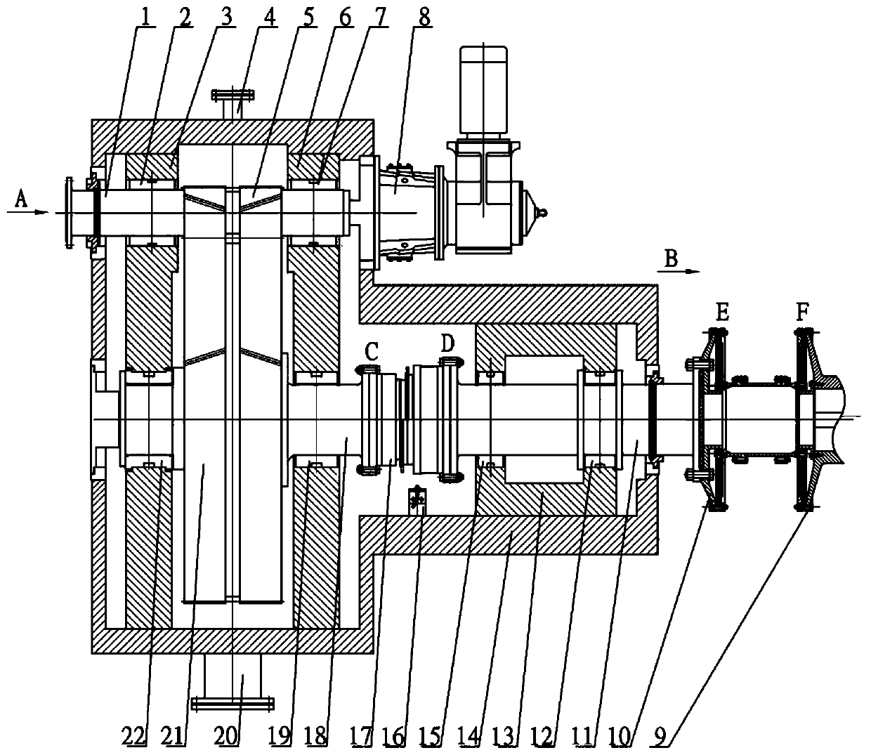
[0025] Specific implementation mode one: combine figure 1 Description of this embodiment, a full-automatic clutch device for an introduction-increase-in-one transformation unit, which includes an input connection shaft 1, a transmission shaft 18, an output connection shaft 11, a housing 14, a crank 8, a pinion 5, and a large gear 21 , synchronous automatic clutch 17;

[0026] The input connection shaft 1, the transmission shaft 18 and the output connection shaft 11 are all arranged in the housing 14, the output connection shaft 11 and the transmission shaft 18 are located on the same axis and parallel to the input connection shaft 1, and the input connection shaft 1 is horizontally arranged on On the upper part of the housing 14, the right end of the input connecting shaft 1 is coaxially connected with the crank 8, the pinion 5 is fixed in the middle of the horizontally arranged input connecting shaft 1, and the transmission shaft 18 and the output connecting shaft 11 are coax...

specific Embodiment approach 2

[0028] Specific implementation mode two: combination figure 1 To illustrate this embodiment, it also includes a bearing, a fully automatic clutch device for a combined introduction and augmentation transformation unit, the right side of the drive shaft 18 is connected to the C end of the synchronous automatic clutch 17, and the left side of the output connection shaft 11 is connected to the synchronous automatic clutch 17. The D end of the clutch 17 is connected. ; Other implementations are the same as in the first embodiment.

specific Embodiment approach 3

[0029] Specific implementation mode three: combination figure 1 Description of this embodiment, a fully automatic clutch device for a combined introduction and augmentation transformation unit, the housing 14 is provided with frame one 3, frame two 6 and frame three 13, frame one 3, frame two 6 and frame body 3 13 are vertically fixed in the housing 14 from left to right; other embodiments are the same as the specific embodiment 1.


PUM


Abstract

The invention relates to a full-automatic clutching device for a drawing and pressurizing integration modification unit and an application method. The full-automatic clutching device for the drawing and pressurizing integration modification unit comprises an asynchronous motor adaptor flange, an insulating coupler, a shell, an output connecting shaft, a sixth bearing, a third frame body, a fifth bearing, a position detecting sensor, a synchronous automatic clutch, a transmission shaft, a fourth bearing, an oil outlet, a large gear, a third bearing, a jigger, a second bearing, an input connecting shaft, a second frame body, a small gear, an oil inlet, a first frame body and a first bearing. The unit is applied to an air drawing fan and a turbine unit, the hidden danger problems that after aturbine and an asynchronous motor are used in the unit at the same time, electro-corrosion possibly occurs, a rotor is heated unevenly and bent are prevented and solved, the integration degree is high, the function is more complete, the bearing ability is high, and the device can be flexibly applied to working conditions of high speed and heavy loads and is more applicable to the modification unit integrating the air drawing fan and a desulfuration and pressurization fan of a thermal power plant.

Description

technical field [0001] The invention relates to a combined transformation unit of an induced draft fan and a desulfurization booster fan in a thermal power plant, in particular to a fully automatic clutch device and an application method for the combined transformation unit of an induced draft fan and a desulfurization booster fan. Background technique [0002] According to national environmental protection requirements, new thermal power plants should simultaneously build desulfurization and denitrification devices, and the flue gas will be discharged into the atmosphere after passing through the desulfurization and denitrification devices. A power plant built two 1000MW ultra-supercritical coal-fired units in 2010. The desulfurization and denitrification devices were installed simultaneously in the project, and the induced draft fan and booster fan were installed separately. The pressure head of the booster fan overcomes the resistance of the desulfurization system. [000...

Claims


Application Information

Patent Timeline
Patent Type & Authority Applications(China)
IPC IPC(8): F01D15/08F01D15/12F01D25/36F04D25/08F16D43/04
CPCF01D15/08F01D15/12F01D25/36F04D25/08F16D43/04
Inventor 仇实左晓镭王勇帆高旭文罗萌邓广琳朱振荣周金阳徐巍
Owner HARBIN GUANGHAN POWER TRANSMISSION
Why Eureka
Try Eureka