Power system of crawler tractor

A technology for power systems and tractors, which is applied to motor vehicles, crawler vehicles, control devices, etc., can solve the problems of poor structural stability, high damage rate, maintenance cost and difficulty, and reduce maintenance costs and avoid internal oil temperature rise. High, less susceptible to impact damage

Active Publication Date: 2017-12-19
HUZHOU SHUANGLI AUTOMATION TECH EQUIP
View PDF5 Cites 0 Cited by
  • Summary
  • Abstract
  • Description
  • Claims
  • Application Information

AI Technical Summary

Problems solved by technology

[0005] The technical purpose of the present invention is to provide a power system of a crawler tractor to solve the problems of poor structural stability, high damage rate, maintenance cost and difficulty of traditional crawler tractors

Method used


Image

  • Power system of crawler tractor
  • Power system of crawler tractor

Examples


Embodiment Construction

[0038] Below in conjunction with accompanying drawing, the present invention will be further described by specific embodiment:

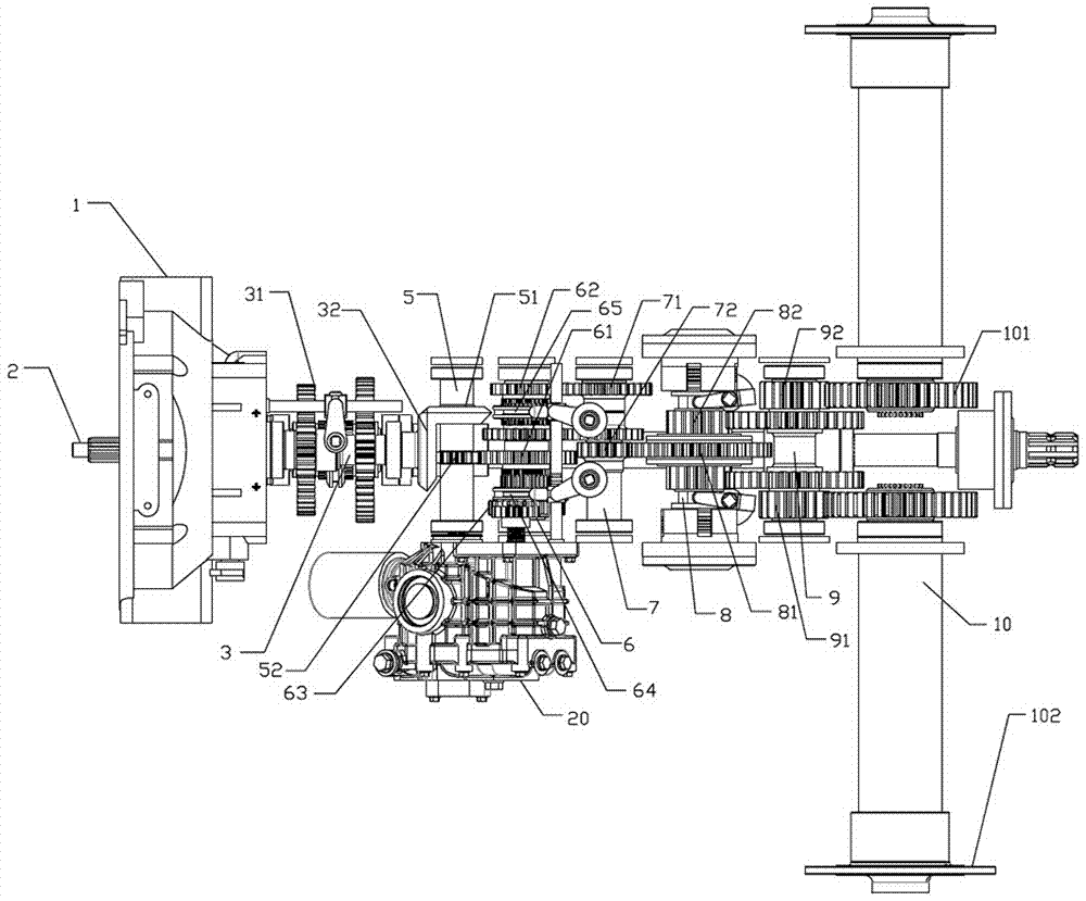
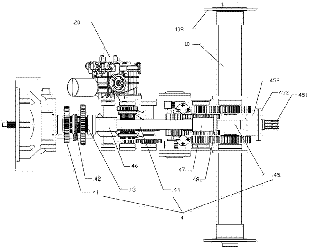
[0039] See figure 1 , figure 2 , a power system of a crawler tractor, including an engine, a clutch 1 and an input shaft 2, the clutch 1 is in the form of a pull rod release fork. The power system also includes a power split mechanism, a power output mechanism, and a driving wheel travel mechanism; the power split mechanism includes a power split shaft 3 connected to the input shaft 2, a power output driving gear 31 located on the power split shaft 3, and an HST power input drive. Gear 32; the power output driving gear 31 is a spur gear, and the power output driving gear 31 is provided with two, which are divided into a high-speed gear and a low-speed gear, and the HST power input driving gear 32 is a bevel gear;

[0040] The power output mechanism includes an output shaft 4 that is arranged in sections and is connected to two adjacent stages of t...


PUM


Abstract

The invention discloses a power system of a crawler tractor. The power system comprises an engine, a clutch and an input shaft, and further comprises a power shunting mechanism, a power output mechanism and a driving wheel walking mechanism. The power system is compact in structure and convenient to use, and the structural strength of an output shaft is improved, the concentricity of a bearing position is ensured, damage is not easy to occur, and the transmission efficiency is improved; a working load of an HST hydrostatic driver is relieved, and the gear position can be rationally arranged according to the actual situation; and a buffering device is used for lightening impact during steering braking, soft start is achieved, and impact damage is avoided; and the advantages of being convenient and simple in the respects of assembling, disassembling and replacing of parts are achieved, and repairing and maintenance difficulty and cost are significantly reduced.

Description

technical field [0001] The invention relates to the technical field of tractor power assembly, in particular to a power system of a crawler tractor. Background technique [0002] At present, domestic crawler tractors generally have the problems of unstable power output shaft performance and short service life. In actual work, after long-term use of the output shaft, there will be a large deviation in the concentricity of the bearing on the shaft, and the output shaft will oscillate in a circle while rotating, which will cause a great burden on the shaft and the box, and will frequently occur. Broken shaft or even the box is torn; and the actual test shows that in many cases, even if the concentricity is still relatively standard, the output shaft of the tractor will still be unable to withstand the torque and easily damaged when the tractor is working. Once the output shaft of these tractors is damaged, the entire gearbox must be disassembled to replace it. Factors such as ...

Claims


Application Information

Patent Timeline
Patent Type & Authority Applications(China)
IPC IPC(8): B62D55/26B60K17/28B60K17/04
CPCB60K17/04B60K17/28B62D55/26
Inventor 施凡方华忠胡聪伟沈敏杰李俊杰
Owner HUZHOU SHUANGLI AUTOMATION TECH EQUIP
Why Eureka
Try Eureka