Supercharge Your Innovation With Domain-Expert AI Agents!

Solenoid valve

A solenoid valve and valve port technology, applied in the field of solenoid valves, can solve problems such as increased travel of the moving iron core, poor valve opening ability, and reduced suction

Active Publication Date: 2017-05-10
ZHEJIANG DUNAN ARTIFICIAL ENVIRONMENT
View PDF5 Cites 8 Cited by
  • Summary
  • Abstract
  • Description
  • Claims
  • Application Information

AI Technical Summary

Problems solved by technology

[0004] The stroke of the moving iron core in the traditional linear pilot valve includes the stroke of the pilot valve and the stroke of the piston. For the solenoid valve that requires a larger flow, the stroke of the piston is required to be larger, which will directly lead to the increase of the stroke of the moving iron core, and the electromagnetic force increases with the distance. Increase the suction and drop sharply, resulting in the larger the specification of the solenoid valve with this structure, the worse the valve opening ability

Method used


Image

  • Solenoid valve
  • Solenoid valve
  • Solenoid valve

Examples


Embodiment 1

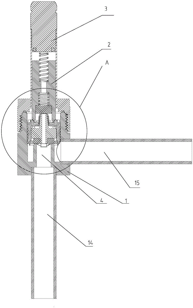
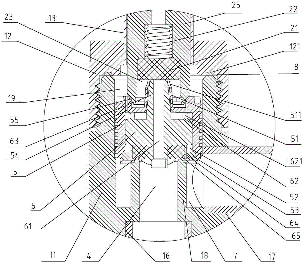
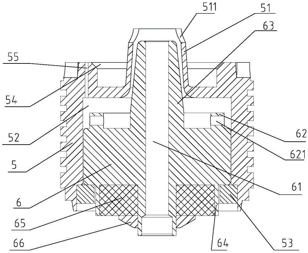
[0033] refer to figure 1 and figure 2 , shows a solenoid valve, including valve body 1, valve body 1 is provided with valve port 4, medium inlet 17 and medium outlet 16, static iron core 3, moving iron core 2 and piston assembly are installed in valve body 1 , the electromagnetic force of the static iron core 3 drives the moving iron core 2 to move, the piston assembly includes a top block 5 and a piston 6, the top block 5 is located between the moving iron core 2 and the valve port 4, and the piston 6 is slidably connected in the top block 5, The piston 6 is provided with a communication hole 61 that leads to the upper space and the lower space of the top block 5. The piston 6 is used to close the valve port 4, and in this state, there is a communication hole between the top block 5 and the valve body 1 that communicates with the medium inlet 17. The cavity 7, the fluid of the medium inlet 17 enters the cavity 7, and a high-pressure area is formed in the cavity 7, and the f...

Embodiment 2

[0044] refer to Figure 7 As shown, a solenoid valve includes a valve body 1, which is provided with a valve port 4, a medium inlet and a medium outlet, and a static iron core, a moving iron core 2 and a piston assembly are installed in the valve body 1, and the static iron core The electromagnetic force drives the moving iron core 2 to move. The piston assembly includes a top block 5 and a piston 6. The top block 5 is located between the moving iron core 2 and the valve port 4. The piston 6 is slidably connected in the top block 5. The piston 6 is provided with The communication hole 61 that connects the upper space and the lower space of the top block 5, the piston 6 is used to close the valve port 4, and in this state, a cavity 7 communicating with the medium inlet is formed between the top block 5 and the valve body 1. The pressure in 7 and the action of the moving iron core 2 drive the top block 5 to move relative to the valve port 4, and the piston 6 moves with the top b...


PUM


Abstract

The invention discloses a solenoid valve, and belongs to the field of control valves. The technical problem that the valve opening capacity of a solenoid valve in the prior art is insufficient is solved. The solenoid valve is provided and comprises a valve body, a valve opening, a medium inlet and a medium outlet are formed in the valve body, a static iron core, a movable iron core and a piston assembly are installed in the valve body, and the piston assembly comprises an ejection block and a piston; the ejection block is located between the movable iron core and the valve opening, the piston is connected into the ejection block in a sliding manner, and a communication hole for communicating upper space and lower space of the ejection block is arranged in the piston; the piston is used for sealing the valve opening, and a cavity communicated with the medium inlet is formed between the ejection block and the valve body; and pressure in the cavity and motion of the movable iron core drive the ejection block to move relative to the valve opening, and the piston moves along with the ejection block to open or close the valve opening.

Description

[0001] 【Technical field】 [0002] The invention relates to a solenoid valve. [0003] 【Background technique】 [0004] The stroke of the moving iron core in the traditional linear pilot valve includes the stroke of the pilot valve and the stroke of the piston. For the solenoid valve that requires a larger flow, the stroke of the piston is required to be larger, which will directly lead to the increase of the stroke of the moving iron core, and the electromagnetic force increases with the distance. Increase the suction force and drop sharply, resulting in the larger the specification of the solenoid valve with this structure, the worse the valve opening ability. [0005] 【Content of invention】 [0006] The technical problem solved by the invention is to provide a solenoid valve to enhance the valve opening capability. [0007] In order to solve the problems of the technologies described above, the present invention adopts the following technical solutions: [0008] A solenoid ...

Claims


Application Information

Patent Timeline
IPC IPC(8): F16K31/06F16K1/32F16K27/02
CPCF16K1/32F16K27/029F16K31/0675
Inventor 俞舟王定军
Owner ZHEJIANG DUNAN ARTIFICIAL ENVIRONMENT
Features
  • R&D
  • Intellectual Property
  • Life Sciences
  • Materials
  • Tech Scout
  • Unparalleled Data Quality
  • Higher Quality Content
  • 60% Fewer Hallucinations
Learn More