Control valve assembly

A technology for controlling valves and components, applied in engine components, machines/engines, charging systems, etc., can solve the problems of large spring force of valve components, increased cost of solenoid valves, and increased driving requirements, and achieve volume reduction and driving requirements. The effect of reducing, reducing the electromagnetic force requirement

Pending Publication Date: 2021-10-26
钧风电控科技泰州有限责任公司
View PDF0 Cites 0 Cited by
  • Summary
  • Abstract
  • Description
  • Claims
  • Application Information

AI Technical Summary

Problems solved by technology

This results in a higher spring force on the valve assembly and also increases the electromagnetic force required to open the valve
This drives up the cost, size and actuation requirements of solenoid valves

Method used


Image

  • Control valve assembly
  • Control valve assembly
  • Control valve assembly

Examples


Embodiment Construction

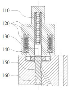
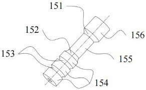
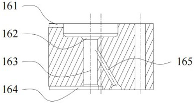
[0018] like Figure 1 to Figure 4 As shown, a control valve assembly adopts a new structural design. When in use, the hydraulic pressure generated by the high-pressure fluid on the lower surface is opposite to the hydraulic pressure on the upper surface, and the two hydraulic forces cancel each other out. Therefore, only a small The upper spring force of the valve stem can maintain the cone surface on the seat surface, the corresponding electromagnetic force requirement is reduced, the cost of the solenoid valve is reduced, the size is reduced, the driving requirement is reduced, the overall durability is stronger during use, and the service life is longer , the use safety is more reliable, and it can have more reliable use stability. It includes a valve body 160, the valve body 160 is provided with a valve body middle hole 163, the upper end of the valve body middle hole 163 is a seat surface 162, and the lower end of the valve body 160 is connected to the bottom of the valve...


PUM


Abstract

The invention relates to the technical field of high-pressure fuel injection valves, in particular to a control valve assembly. According to the technical scheme, the check valve assembly comprises a valve body, the valve body is provided with a valve body middle hole, the upper end of the valve body middle hole is a seat face, the lower end of the valve body and the bottom of the valve body middle hole are provided with a circulation groove communicated with the outside of the valve body, a valve rod is installed in the valve body middle hole, an annular groove used for fluid circulation is formed in the middle of the outer side of the valve rod in the vertical direction, the upper portion and the lower portion, located in the annular groove, of the valve rod are an upper end cylindrical face and a lower end cylindrical face respectively, and an upper connecting face is formed between the upper end cylindrical face and the annular groove. The control valve assembly has the advantages that the electromagnetic valve cost is reduced, the size is reduced, the driving requirement is reduced, the overall durability is higher during use, the service life is longer, the use safety is more reliable, and the more reliable use stability can be achieved.

Description

technical field [0001] The invention relates to the technical field of high-pressure fuel injection valves, in particular to a control valve assembly. Background technique [0002] In today's world, powertrain pollutant emissions have become the focus of the international community. With the increasingly stringent emission regulations, the fuel pressure of electronically controlled fuel injection systems has gradually increased. In order to realize the sealing and precise control of ultra-high pressure fuel, a higher electromagnetic force is required, and the cost of the corresponding magnetic material is higher and the installation space requirement is larger. Ball valves, plane valves and other valve assembly structures commonly used today all face this problem. This leads to a sharp increase in the cost of the electronically controlled fuel injection system and poor installation adaptability. [0003] In the prior art, the sealing parts such as steel ball, valve needle ...

Claims


Application Information

Patent Timeline
Patent Type & Authority Applications(China)
IPC IPC(8): F02M63/00F02M51/06
CPCF02M63/0073F02M63/0017F02M51/061
Inventor 于建锋王景致徐小松
Owner 钧风电控科技泰州有限责任公司
Why Eureka
Try Eureka