Floating ball valve structure

A ball float valve and ball float technology, applied in the field of ball float valves, can solve the problems of complex structure and high manufacturing cost, and achieve the effects of simple structure, low production cost and convenient use

Inactive Publication Date: 2017-05-10
苏州盟通利环境科技有限公司
View PDF8 Cites 0 Cited by
  • Summary
  • Abstract
  • Description
  • Claims
  • Application Information

AI Technical Summary

Problems solved by technology

The structure of this kind of float valve is relatively complicated, and the manufacturing cost is relatively high.

Method used


Image

  • Floating ball valve structure
  • Floating ball valve structure

Examples


Embodiment Construction

[0013] The following specific examples illustrate the implementation of the present invention. Those skilled in the art can easily understand other advantages and effects of the present invention from the content disclosed in this specification.

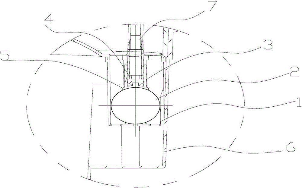
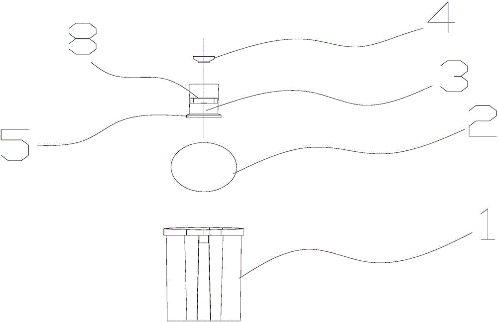
[0014] See figure 1 , 2 . It should be noted that the structures, proportions, sizes, etc. shown in the accompanying drawings in this specification are only used to match the content disclosed in the specification for people familiar with this technology to understand and read, and are not intended to limit the implementation of the present invention Limited conditions, so it has no technical significance. Any structural modification, proportional relationship change or size adjustment should still fall under the present invention without affecting the effects and objectives that can be achieved by the present invention. The disclosed technical content must be within the scope of coverage. At the same time, the terms such as "upper", "...


PUM


Abstract

The invention provides a floating ball valve structure which comprises a floating ball shell. A through hole is formed in the floating ball shell. A floating ball is arranged inside the floating ballshell. A guiding sleeve is arranged above the floating ball. A sealing gasket is arranged inside the guiding sleeve. When the floating ball valve structure is in use, the floating ball shell is fixedinto a water tank, a water injection pipe is inserted into the guiding sleeve, and due to the fact that the through hole is formed in the floating ball shell, it can be ensured that the water level inside the floating ball shell is flush with the water level inside the water tank. Along with increase of the water level inside the water tank, the floating ball drives the guiding sleeve to be liftedcorrespondingly, the sealing gasket inside the guiding sleeve will seal the water injection pipe, and then the purpose of controlling the water level can be achieved. The floating ball valve has theadvantages of being simple in structure, convenient to use and low in production cost.

Description

Technical field [0001] The invention relates to a floating ball valve, in particular to a floating ball valve structure capable of realizing water level control. Background technique [0002] Floating ball valves are widely used in water level control, water level detection and other fields. In order to achieve the purpose of water level control, the structure of existing float valves is relatively complicated. For example, the Chinese invention patent (Patent No.: 201510552194.0) discloses a floating ball valve. The float valve includes: a valve body with an upper water cavity, a middle water cavity and a lower water cavity. The valve body is provided with an upper liquid inlet connecting the upper water cavity and the middle water cavity, and a lower liquid inlet communicating the lower water cavity and the middle water cavity. Hole, the liquid inlet connected with the upper water cavity and the liquid outlet connected with the middle water cavity; the drainage pipe, the draina...

Claims


Application Information

Patent Timeline
Patent Type & Authority Applications(China)
IPC IPC(8): F16K31/20
CPCF16K31/20
Inventor 许正荣麻超徐斌
Owner 苏州盟通利环境科技有限公司
Why Eureka
Try Eureka