
Gas sensor evaluation and calibration system

A gas sensor and calibration system technology, which is applied in the direction of standard gas analyzers, gas analyzer structure details, gas mixture analysis, etc., can solve the problems of restricting encrypted observation applications, different sizes of gas sensors, and high detection limit, etc., to achieve convenience The effect of fixed and overall transfer, ensuring data reliability, and facilitating system operation

Pending Publication Date: 2017-05-10
TSINGHUA UNIV
View PDF8 Cites 22 Cited by
  • Summary
  • Abstract
  • Description
  • Claims
  • Application Information

AI Technical Summary

Problems solved by technology

[0002] Conventional gas monitoring equipment in the traditional atmosphere is bulky, expensive, and complicated to install and maintain, which limits its large-scale encrypted observation applications. At present, more and more miniaturized and low-cost gas sensors are emerging on the market. Portable gas sensors based on gas sensors are emerging. Or network monitors, intensive observation of air quality has become a trend
[0003] Compared with traditional online conventional gas monitors, gas sensor-based monitors have the advantages of fast response, small size, low cost, and less maintenance. Environmental factors have a big impact
Therefore, it is necessary to build a system for scientific and reasonable evaluation and calibration of gas sensors. For example, the invention patent of a gas sensor calibration tool and calibration method (publication number 105572307A), each sensor and the adapter base are sealed by an O ring. Fixed, the base is calibrated through series and parallel connections, but this method is not universal, different gas sensors have different sizes and interfaces, and the use of O-ring seals may cause leakage of individual gas sensors, and The calibration tooling did not perform humidity pre-treatment and could not perform temperature and humidity adjustment.

Method used


Image

  • Gas sensor evaluation and calibration system
  • Gas sensor evaluation and calibration system

Examples


Embodiment Construction

[0019] In order to make the objectives, technical solutions and advantages of the present invention clearer, the technical solutions in the embodiments of the present invention will be described in more detail below in conjunction with the drawings in the embodiments of the present invention. In the drawings, the same or similar reference numerals denote the same or similar elements or elements having the same or similar functions throughout. The described embodiments are some, but not all, embodiments of the invention. The embodiments described below by referring to the figures are exemplary and are intended to explain the present invention and should not be construed as limiting the present invention. Based on the embodiments of the present invention, all other embodiments obtained by persons of ordinary skill in the art without creative efforts fall within the protection scope of the present invention. Embodiments of the present invention will be described in detail below ...


PUM


Abstract

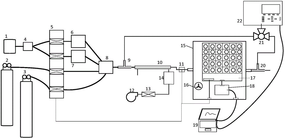
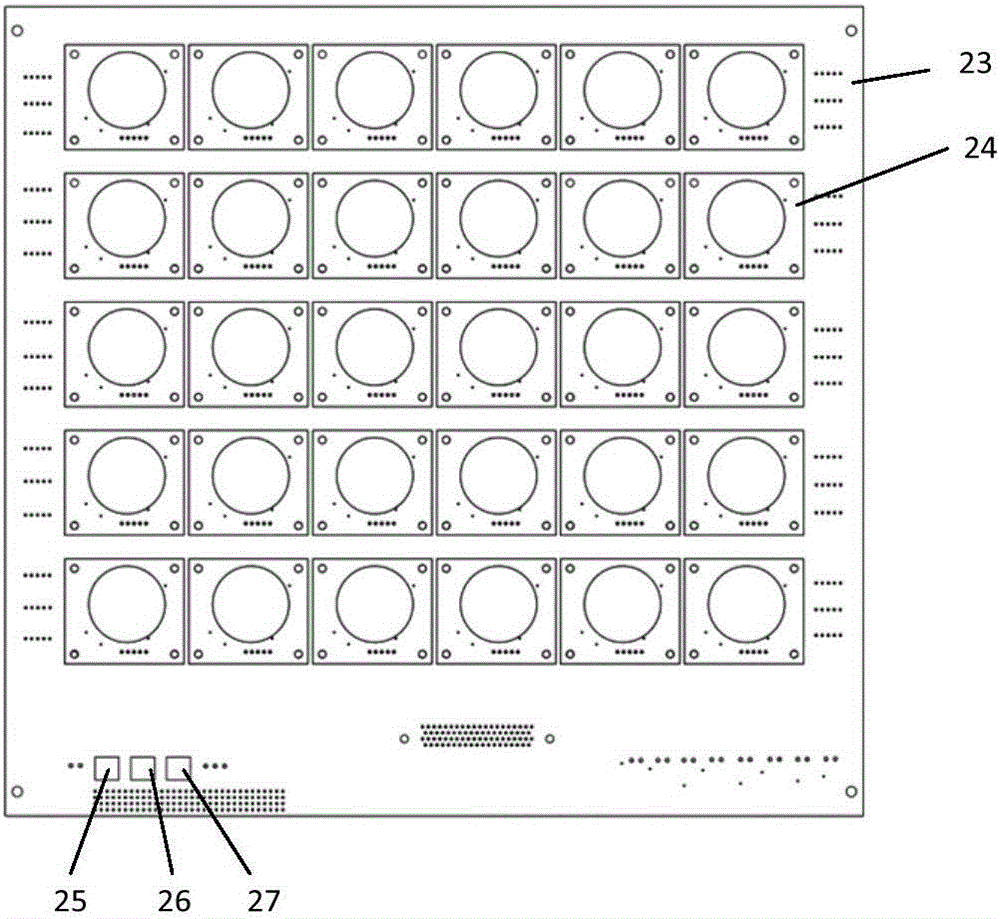
The invention discloses a gas sensor evaluation and calibration system. The gas sensor evaluation and calibration system comprises a gas distribution unit, a conditioning unit, a calibration unit and a reference unit, wherein a gas outlet of the gas distribution unit is connected with the conditioning unit, the gas distribution unit is used for configuring calibration gases of different concentrations, the conditioning unit is used for carrying out humidity control on the calibration gases, the conditioning unit is connected with the calibration unit, the calibration gases passing through the conditioning unit enter the calibration unit and calibrate gas sensors, and the reference unit can be separately connected with a gas inlet of the conditioning unit and a gas outlet of the calibration unit in a switch valve manner and is used for monitoring the concentrations of the gases before entering the calibration unit and after leaving the calibration unit in real time. The gas sensor evaluation and calibration system disclosed by the invention has the advantages of convenient operation, high safety and high extendability, and can be used for evaluating and calibrating the gas sensors in batches.

Description

technical field [0001] The invention relates to the technical field of environmental monitoring, in particular to a gas sensor evaluation and calibration system. Background technique [0002] Conventional gas monitoring equipment in the traditional atmosphere is bulky, expensive, and complicated to install and maintain, which limits its large-scale encrypted observation applications. At present, more and more miniaturized and low-cost gas sensors are emerging on the market. Portable gas sensors based on gas sensors are emerging. Or network monitors, intensive observation of air quality has become a trend. [0003] Compared with traditional online conventional gas monitors, gas sensor-based monitors have the advantages of fast response, small size, low cost, and less maintenance. Environmental factors have a great influence. Therefore, it is necessary to build a system for scientific and reasonable evaluation and calibration of gas sensors. For example, the invention patent...

Claims


Application Information

Patent Timeline
IPC IPC(8): G01N33/00
CPCG01N33/0006G01N33/007Y02A50/20
Inventor 蒋靖坤张强
Owner TSINGHUA UNIV
Learn More