Antenna detection system and method

An antenna detection and antenna technology, applied in the field of detection systems, can solve problems such as affecting the communication quality and yield of wireless communication products, unable to actually reflect the antenna gain value, etc., to achieve the effect of improving the efficiency and the quality of the antenna

Inactive Publication Date: 2017-05-10
SHENXUN COMP KUNSHAN +1
View PDF5 Cites 4 Cited by
  • Summary
  • Abstract
  • Description
  • Claims
  • Application Information

AI Technical Summary

Problems solved by technology

However, the S11 parameter cannot actually reflect the real gain value of the antenna, thus affecting the communication quality and yield of the applied wireless communication products

Method used


Image

  • Antenna detection system and method
  • Antenna detection system and method
  • Antenna detection system and method

Examples


Embodiment Construction

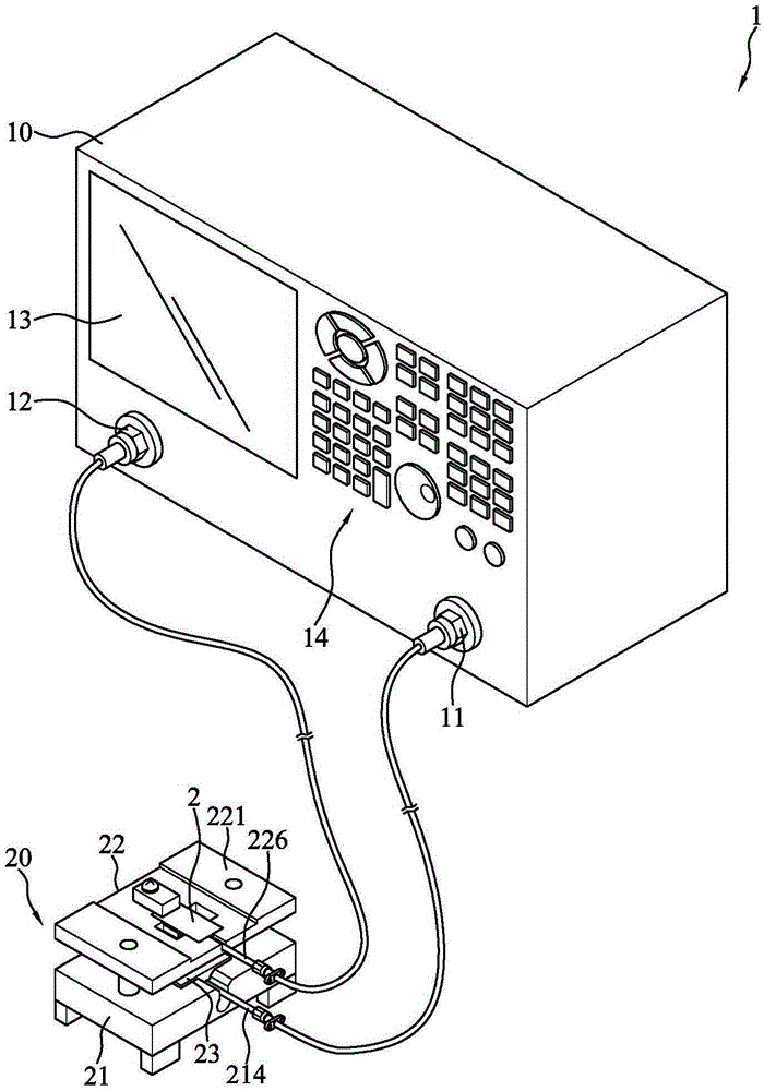
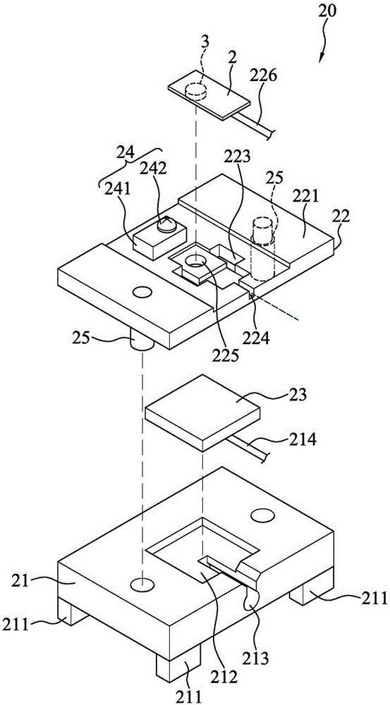
[0020] figure 1 and figure 2 It is a perspective view and an exploded perspective view of an embodiment of the antenna detection system of the present invention. refer to figure 1 and figure 2 , the antenna detection system 1 is used to detect the antenna 2 to be tested. In some embodiments, the antenna under test 2 is preferably an active antenna, but may also be a passive antenna or other types of antennas, which is not limited. In this embodiment, the antenna testing system 1 includes a network analyzer 10 and a testing device 20 .

[0021] The network analyzer 10 is used to measure the characteristics of various active or passive components. Network analyzer 10 may include more than two ports. For the convenience of description, here, two ports are taken as an example, which are respectively referred to as the first port 11 and the second port 12 below. Wherein, the first port 11 is used for transmitting signals, and the second port 12 is used for receiving signal...


PUM


Abstract

The invention provides an antenna detection system which is used for detecting a to-be-detected antenna. The antenna system comprises a network analyzer and a test device. The test device comprises a first substrate, a second substrate, and a standard antenna. The first substrate and the second substrate are arranged in parallel. The to-be-detected antenna is removably arranged on the second substrate. The standard antenna is fixedly arranged on the first substrate, and is used for receiving a test signal from a first port of the network analyzer and sending a radiation signal according to the test signal. The to-be-detected antenna can receive the radiation signal and transmit a to-be-detected signal to a second port of the network analyzer. The network analyzer gets an S21 parameter according to the test signal and the to-be-detected signal, and compares the S21 parameter with a theoretical value calculated according to the work frequency and fixed distance of the corresponding to-be-detected antenna to output the detection result of the to-be-detected antenna. Through the antenna detection system of the invention, whether the actual gain of a to-be-detected antenna is in accordance with the requirement can be judged quickly and accurately, and the efficiency of detection operation and the quality of antennas are improved significantly.

Description

【Technical field】 [0001] The present invention relates to a detection system and method, in particular to an antenna detection system and method. 【Background technique】 [0002] With the rapid development of the wireless communication industry, the demand for antennas used in the wireless communication industry is also increasing. For example, radios, televisions, mobile phones, etc., all need antennas to transmit sound, video or other data. It can be seen that the quality of the antenna is a very critical factor affecting the quality of communication. Therefore, the inspection process of the antenna after the manufacture is very important. [0003] At present, the main way to measure the antenna is mostly to measure the return loss (S11 parameter) of the antenna through a network analyzer, and then the quality of the antenna is judged by the network analyzer or testers according to the measured return loss. However, the S11 parameter cannot actually reflect the true gain v...

Claims


Application Information

Patent Timeline
Patent Type & Authority Applications(China)
IPC IPC(8): G01R29/10
CPCG01R29/10G01R29/0892
Inventor 李彦庆黄嘉民
Owner SHENXUN COMP KUNSHAN
Why Eureka
Try Eureka