A manufacturing process for ultra-narrow display frame

A production process and display technology, applied in the fields of instruments, nonlinear optics, optics, etc., can solve the problem of difficult to meet the requirements of reducing the ultra-narrow frame and frame, and achieve the effect of reducing display discontinuity, reducing size, and reducing space.

Active Publication Date: 2019-07-26
SHENZHEN KEF IND EQUIP
View PDF6 Cites 0 Cited by
  • Summary
  • Abstract
  • Description
  • Claims
  • Application Information

AI Technical Summary

Problems solved by technology

[0002] In the production process of traditional LCD displays, due to the needs of liquid crystal drivers, the binding position of the driving lines needs to be reserved. The traditional method is to make the TFT glass with lines slightly larger than the upper glass, usually larger than 3~5mm. Exposing the lines that need to be bonded to reserve the bonding position of the drive line, and this will inevitably cause the width of the bonded side to be larger than that of the non-bonded side, making it difficult to meet the requirements of ultra-narrow bezel display for border reduction

Method used


Image

  • A manufacturing process for ultra-narrow display frame
  • A manufacturing process for ultra-narrow display frame
  • A manufacturing process for ultra-narrow display frame

Examples


Embodiment 1

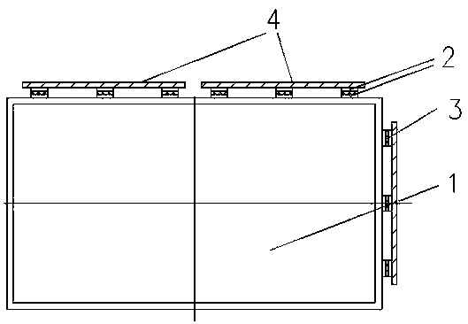
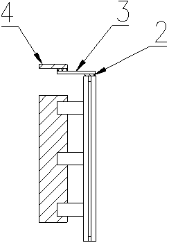
[0029] 1) The upper layer of the display screen is the CF layer, the lower layer is the TFT layer, the liquid crystal conductive medium is coated in the middle, and the polarizer to be attached is printed on the display glass. A laser cutting device is used to cut the edge of the polarizer, the size of the polarizer to be bonded is cut to exceed the display screen by 2mm, the polarizer to be cut is bonded to the display screen, and then the laser is used to align the RGB corners. The polarizer is cut twice to make the size of the polarizer the same as the display screen.

[0030] The upper and lower sides of the display screen are the glass planes of the LCD display screen, and the rest are the sides of the LCD display screen.

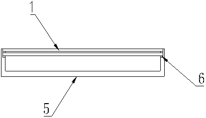
[0031] 2) Plasma cleaning of the bonding surface requires the bonding surface to be grinded to make the finish Ra less than 0.32um, and the straightness and verticality meet the requirements of the display screen. The display screen can be rotated on the be...

Embodiment 2

[0039] 1) The upper layer of the display screen is the CF layer, the lower layer is the TFT layer, the liquid crystal conductive medium is coated in the middle, and the polarizer to be attached is printed on the display glass. A laser cutting device is used to cut the edge of the polarizer, the size of the polarizer to be bonded is cut to exceed the display screen by 2mm, the polarizer to be cut is bonded to the display screen, and then the laser is used to align the RGB corners. The polarizer is cut twice to shrink the polarizer by 0.15mm relative to the display screen.

[0040] The upper and lower sides of the LCD display screen are the glass planes of the display screen, and the rest are the sides of the LCD display screen.

[0041] 2) Plasma cleaning of the bonding surface requires the bonding surface to be grinded to make the finish Ra less than 0.32um, and the straightness and verticality meet the requirements of the display screen. The display screen can be rotated on the be...

Embodiment 3

[0049] 1) The upper layer of the display screen is the CF layer, the lower layer is the TFT layer, the liquid crystal conductive medium is coated in the middle, and the polarizer to be attached is printed on the display glass. A laser cutting device is used to cut the edge of the polarizer. The size of the polarizer to be bonded is cut by 3mm beyond the display screen. The polarizer to be cut is bonded to the display screen, and the polarizer is flush with or opposite to the display screen. The screen is retracted, and then the polarizer is cut twice with the laser based on the RGB corners to make it the same size as the screen.

[0050] The upper and lower sides of the LCD display screen are the glass planes of the display screen, and the rest are the sides of the LCD display screen.

[0051] 2) Plasma cleaning of the bonding surface requires the bonding surface to be grinded to make the finish Ra less than 0.32um, and the straightness and verticality meet the requirements of the ...


PUM


Abstract

The invention discloses a making process for borders of the ultra narrow display screen. The making process comprises the steps of attaching of Polaroid and laser trimming, plasma cleaning of the bonding face, silver paste printing and solidification, attaching and bonding of ACF and PFC, bonding of PFC, encapsulating with UV gum, and assembling in back light. The TFT and CF are made into the same size by the making process, the ITO circuit on TFT is turned over to the side ridged edges of the LCD display screen through the conductive silver paste, further shrinking and stitching of the display screen in size are achieved, the interruptions of displaying are prevented, and the visual sense of the viewer is enhanced.

Description

Technical field [0001] The invention relates to a manufacturing method of an LCD display screen, more specifically, a manufacturing process for an ultra-narrow display screen frame. Background technique [0002] In the production process of traditional LCD display screens, due to the needs of liquid crystal driving, it is necessary to reserve the binding position of the driving circuit. The traditional method is to make the TFT glass with the circuit slightly larger than the upper glass, usually larger than 3~5mm. Expose the wiring that needs to be bonded to leave the bonding position of the drive circuit. This approach will inevitably cause the width of the bonding side to be larger than that of the non-bonding side, which makes it difficult to meet the requirements of ultra-narrow bezel display for reducing the bezel . The solution of the present invention adopts vertical bonding. By controlling the thickness of ACF, FPC and UV sealant, the space occupied by bonding is greatly...

Claims


Application Information

Patent Timeline
Patent Type & Authority Patents(China)
IPC IPC(8): G02F1/1333
CPCG02F1/1333G02F1/133308G02F1/133351
Inventor 郑春晓吴永正
Owner SHENZHEN KEF IND EQUIP
Why Eureka
Try Eureka