
Frameless display module set and terminal device with same

A display module and borderless technology, applied in light guides, optics, instruments, etc., can solve problems such as light loss, achieve the effects of improving brightness, saving costs, and avoiding light loss

Inactive Publication Date: 2018-08-21
SHANGHAI MORUAN COMM TECH
View PDF10 Cites 0 Cited by
  • Summary
  • Abstract
  • Description
  • Claims
  • Application Information

AI Technical Summary

Problems solved by technology

[0005] The technical problem to be solved by the present invention is to overcome the defect of light loss caused by light leakage from the side of the light guide plate in the frameless display module in the prior art during the light transmission process, and disclose a frameless display module and a terminal device with it

Method used


Image

  • Frameless display module set and terminal device with same
  • Frameless display module set and terminal device with same
  • Frameless display module set and terminal device with same

Examples


Embodiment 1

[0071] Embodiment 1 discloses a borderless display module 100 .

[0072] Such as Figure 4 As shown, the borderless display module 100 includes a light guide plate 110 having a light incident surface 111 , a light exit surface 112 , a side surface 113 , a bottom surface 114 , a bottom reflection sheet 120 and a side reflection sheet 130 . Wherein, the light emitting surface 112 and the bottom surface 114 are respectively connected to the two ends of the light incident surface 111, and the side surfaces 113 are connected to both sides of the light incident surface 111 and between the light emitting surface 112 and the bottom surface 114; the bottom reflection sheet 120 faces the bottom surface 114 The side reflector 130 is connected to the surface of the bottom reflector 120 facing the bottom surface 114 , the side reflector 130 is attached to the side 113 , and the side reflector 130 is used to reflect light projected on the side 113 . Figure 4 Only a schematic cross-section...

Embodiment 2

[0075] The difference between the borderless display module 100 disclosed in Embodiment 2 and Embodiment 1 is that, in order to achieve borderless display and higher light utilization efficiency, the light guide plate 110 used in the borderless display module 100 A manner of assembling or connecting with other components in the borderless display module 100 . The specific implementation is as described below.

[0076] see Figure 5 to Figure 8 , the light guide plate 110 has a light incident surface 111 , a light exit surface 112 , a side surface 113 , a bottom surface 114 , a bottom reflection sheet 120 and a side reflection sheet 130 . Based on the structure of the borderless display module 100 disclosed in the first embodiment, in the second embodiment, the bottom reflection sheet 120 is pasted on the bottom surface 114 for reflecting light projected on the bottom surface 114 . The side reflector 130 can already prevent light leakage from the side 113 of the light guide p...

Embodiment 3

[0087] Such as Figure 9 As shown, Embodiment 3 of the present invention discloses a terminal device, which can apply the borderless display module provided in the above embodiment.

[0088] The terminal device of this embodiment 3 includes a housing 200, a central processing unit 300, the borderless display module 100 and an access module 400 in the second embodiment, the central processing unit 300 is installed inside the housing 200, and the borderless display module 100 Installed on the surface of the housing 200 , the access module 400 is installed on the housing 200 . Wherein, the access module 400 can be located on the same surface of the housing 200 as the borderless display module 100 , or can be located on a different surface of the housing 200 from the borderless display module 100 . The access module 400 communicates with the central processor 300, and the central processor 300 communicates with the borderless display module 100. The access module 400 is used to i...


PUM

PropertyMeasurementUnit
refractive indexaaaaaaaaaa

Abstract

The invention discloses a frameless display module set and a terminal device with the same. The frameless display module set comprises a light guide plate; the light guide plate is provided with a light incoming surface, a light exiting surface, a side surface, a bottom surface, a bottom reflection sheet and a side reflection sheet; the light exiting surface and the bottom surface are respectivelyconnected with two ends of the light incoming surface; the side surface is connected with two sides of the light incoming surface and is also connected between the light exiting surface and the bottom surface; the bottom reflection sheet faces the bottom surface; the side reflection sheet is connected with a surface of the bottom reflection sheet, wherein the surface of the bottom reflection sheet faces the bottom surface; the side reflection sheet is attached to the side surface; and the side reflection sheet is used for reflecting light projected on the side surface. The terminal device comprises the frameless display module set. According to the frameless display module set and the terminal device with the same, the side reflection sheet is attached to the side surface of the light guide plate, so that light loss caused by the light leakage of the side surface of the light guide plate can be avoided, and therefore, optical efficiency can be improved, and the display brightness of the terminal device can be improved; and the rigidity of the light guide plate is directly utilized to support an optical film and a liquid crystal display panel, and therefore, cost can be saved, anda frameless effect can be achieved.

Description

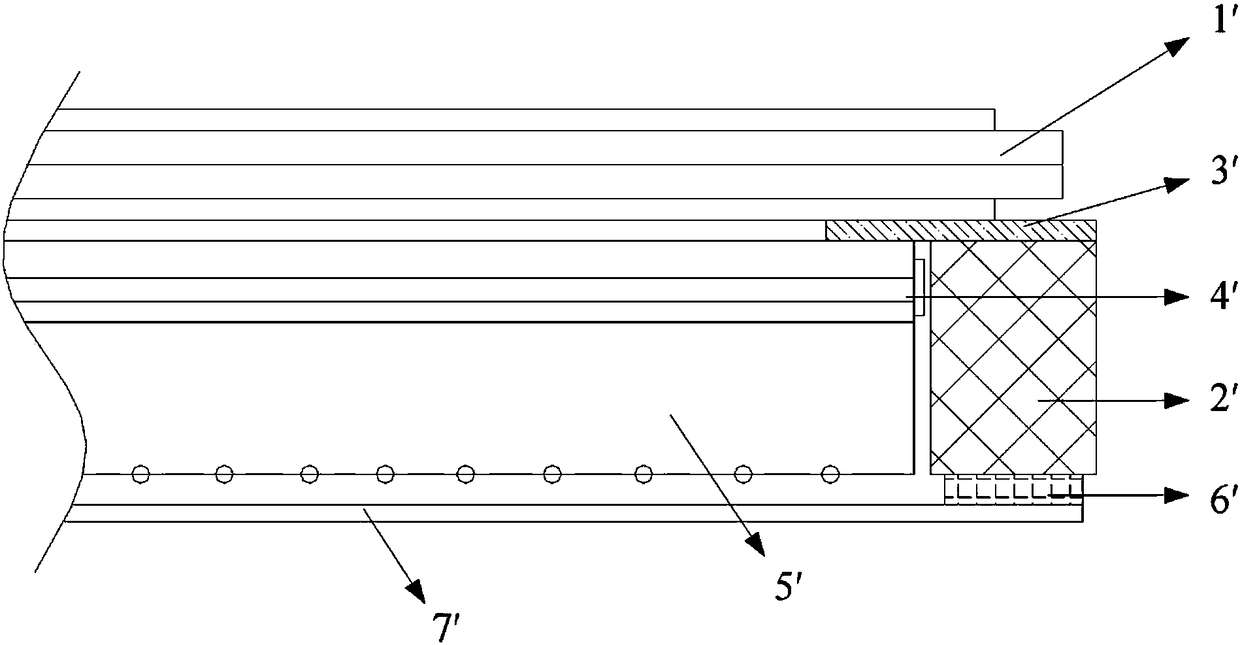
technical field [0001] The invention relates to the technical field of light-emitting devices for light and thin electronic devices, in particular to a frameless display module and a terminal device having the same. Background technique [0002] Existing borderless liquid crystal display modules such as figure 1 As shown, it is generally composed of a liquid crystal panel 1', a plastic frame 2', a light-shielding glue 3', an optical film 4', a light guide plate 5', a double-sided adhesive tape 6', a reflector 7' and a light source 8'. The reflective sheet 7' is attached to the plastic frame 2' through the double-sided adhesive tape 6' to serve as the display module carrier, the light guide plate 5', the optical film 4', the light-shielding adhesive 3' and the liquid crystal panel 1' are stacked in sequence, and the light source 8' emits The light emitted through the light guide plate 5' finally achieves the purpose of display. [0003] As the width of the liquid crystal di...

Claims


Application Information

Patent Timeline
Patent Type & Authority Applications(China)
IPC IPC(8): G02B6/00G02F1/1335
Inventor 马晓康
Owner SHANGHAI MORUAN COMM TECH
Learn More