Jointed wall signal window display control method

A display control method and signal window technology, applied in the direction of digital output to display equipment, instruments, electrical digital data processing, etc., can solve the problem of low flexibility, the inability to freely adjust the size or position of the signal window on the virtual wall, and the inability to do From fine-tuning and other issues, to achieve easy and flexible control, improve work efficiency and product experience, and simplify daily scene editing

Inactive Publication Date: 2017-05-10
GUANGDONG VTRON TECH CO LTD
View PDF7 Cites 21 Cited by
  • Summary
  • Abstract
  • Description
  • Claims
  • Application Information

AI Technical Summary

Problems solved by technology

In the large-screen splicing wall system based on B / S mode, the signal window display control is mainly through obtaining the layout information of each display unit on the large-screen splicing wall, generating the corresponding virtual wall on the client browser page, and then Each signal window is drawn on the wall, and the user controls the scaling or shifting of the signal window on the virtual wall by clicking the preset operation button on the page with the mouse, and the server reads the operation command input by the user on the selected window on the virtual wall, Map the windows displayed on the virtual wall to the splicing wall, so as to realize the control of the signal window on the splicing wall. As disclosed in the Chinese invention patent application with the application number of 201510946846.9, this method is relatively simple for the client. However, because the ratio of zooming or shifting each time the operation button is clicked is a fixed value, when the user controls the signal window on the virtual wall, he cannot make fine adjustments smaller than the fixed value, and cannot freely adjust the virtual wall. The size or position of the signal window, and it may take multiple clicks on the operation button to zoom or shift the window to its desired position, which is less flexible and inconvenient to operate

Method used


Image

  • Jointed wall signal window display control method
  • Jointed wall signal window display control method
  • Jointed wall signal window display control method

Examples


Embodiment

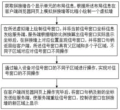
[0017] Such as figure 1 As shown, a video wall signal window display control method, including:

[0018] Obtain the layout information of each display unit of the mosaic wall, and draw a virtual wall by simulating the mosaic wall on the webpage of the client browser according to the layout information;

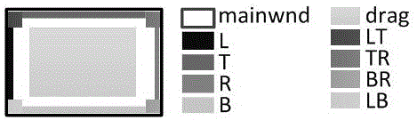
[0019] Draw a signal window on the virtual wall, and send the coordinate information of the current signal window to the server. After the server converts the actual display coordinates of the signal window according to the scaling ratio, the signal window is presented at the corresponding position on the splicing wall, and the window handle is Returning to the client, the signal window has a parent area and multiple sub-areas, and different sub-areas correspond to different operations of the signal window;

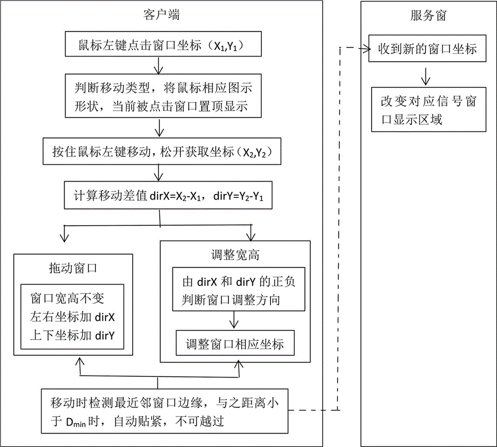
[0020] Through the operation of the input device on different sub-areas of the signal window, different operations on the signal window are realized;

[0021] After the...


PUM


Abstract

The invention discloses a jointed wall signal window display control method. A father area and sub-areas are established on a signal window, different operation on the signal window is achieved through the operation of input equipment on different sub-areas of the signal window, the functions of free dragging and releasing, free size adjustment and adjacent window magnetic attraction of the window are achieved, control over the signal window is easier and more flexible, and intelligent fine adjustment is convenient; user operation is greatly simplified, work efficiency is improved, and the user experience effect is good.

Description

technical field [0001] The invention relates to the field of splicing walls, in particular to a display control method of a splicing wall signal window. Background technique [0002] With the rapid development of video display technology, traffic monitoring, video conferencing, report display and other work are increasingly using large-screen splicing wall systems for real-time multi-screen display. Management platform for real-time scheduling. The advantage of the large-screen splicing wall system is that it can dynamically and comprehensively display various computer signals, video signals, and network signals on a unified logical screen. How to allow users to easily and flexibly control and dispatch the display signals has become an urgent problem to be solved. question. [0003] At present, the display control of the video wall signal window mainly adopts C / S (client / server) or B / S (browser / server) mode. The former client needs to install special software, and addition...

Claims


Application Information

Patent Timeline
Patent Type & Authority Applications(China)
IPC IPC(8): G06F3/14G06F3/0486G06F3/0484
CPCG06F3/1446G06F3/04845G06F3/0486G06F3/1423
Inventor 彭曦
Owner GUANGDONG VTRON TECH CO LTD
Why Eureka
Try Eureka