
Signal lamp control method and system based on accumulated snow monitoring stereo perception

A technology of signal light control and three-dimensional perception, which is applied in the traffic control system of road vehicles, traffic control system, traffic signal control, etc. It can solve the problems of unrecognizable snow cover at the stop line and the inability to detect whether there is snow at the intersection in real time, etc.

Inactive Publication Date: 2017-05-10
北京博研智通科技有限公司
View PDF7 Cites 0 Cited by
  • Summary
  • Abstract
  • Description
  • Claims
  • Application Information

AI Technical Summary

Problems solved by technology

[0003] The present invention aims to solve the problems in the prior art, one is that it is impossible to detect in real time whether the intersection is snow-covered; the other is whether the stop line is covered by snow and cannot be identified; In order to solve the problem of plane detection of the vehicle trajectory at the intersection, a method and system for signal light control based on snow monitoring and stereo perception are proposed

Method used


Image

  • Signal lamp control method and system based on accumulated snow monitoring stereo perception
  • Signal lamp control method and system based on accumulated snow monitoring stereo perception
  • Signal lamp control method and system based on accumulated snow monitoring stereo perception

Examples


Embodiment 1

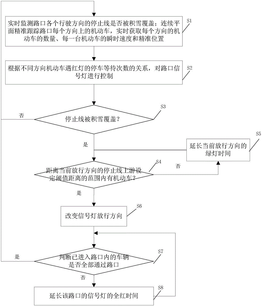
[0058] This embodiment provides a method for signal light control based on snow monitoring stereo perception, such as figure 1 shown, including the following steps:

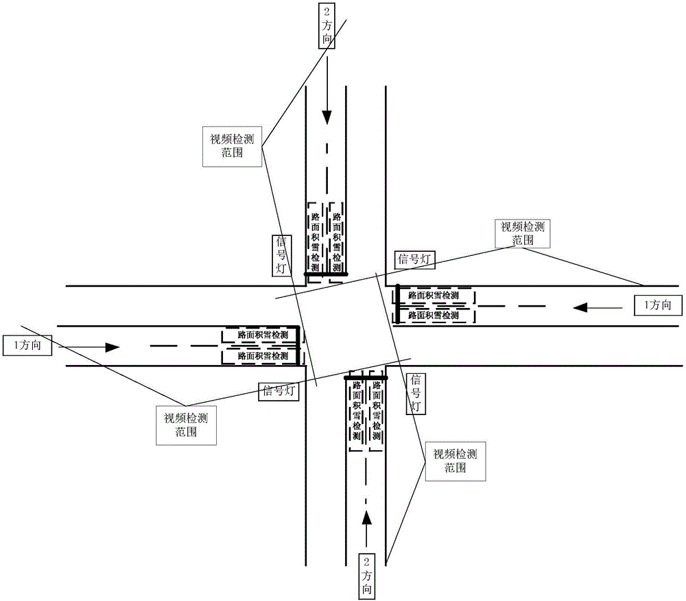
[0059] S1: Real-time monitoring of whether the stop line in each direction of the intersection is covered by snow; the continuous plane accurately tracks the motor vehicles in each direction of the intersection, and obtains the number of motor vehicles in each direction, the instantaneous speed and the speed of each motor vehicle in real time Accurate location; when the instantaneous speed of the motor vehicle continues to be zero, it is determined that the motor vehicle is in a stopped state; the intersection is as follows figure 2 As shown, among them, the snow detection can be realized by using the existing snow detection technology. In this step, the result of snow detection is obtained directly. As shown in the figure, snow detection devices are installed at the entrances in each direction, and the video ...

Embodiment 2

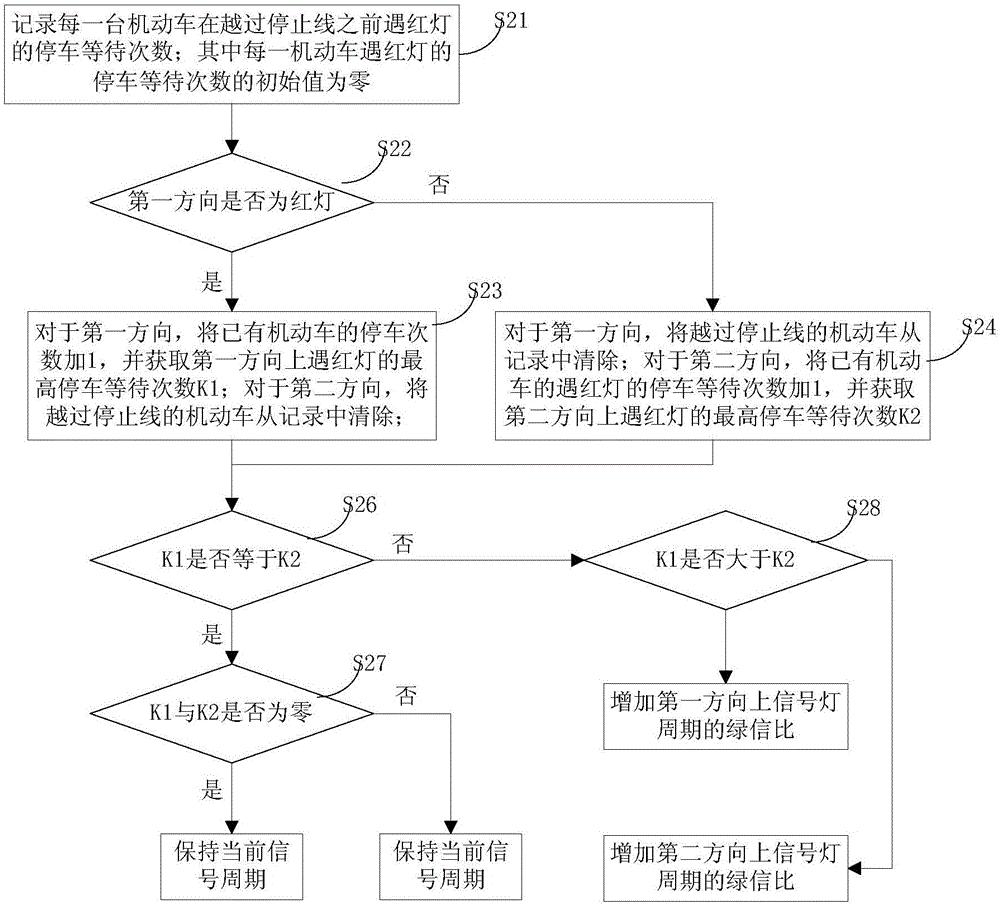
[0070] In this embodiment, on the basis of Embodiment 1, step S2 can be realized in the following way, as image 3 Shown:

[0071] S21: Record the number of times each motor vehicle waits to stop at a red light before crossing the stop line; wherein the initial value of the number of times each motor vehicle stops to wait at a red light is zero; specifically, a driving state table can be established to record each The driving state of a motor vehicle, the driving state includes the number of times each motor vehicle stops and waits at a red light before crossing the stop line; The initial value of parking waiting times is zero;

[0072] S22: Determine whether the first direction is a red light, if so, execute step S23, otherwise execute step S24;

[0073] S23: For the first direction, add 1 to the number of parking times of existing motor vehicles, and obtain the highest number of times K1 of waiting for red lights in the first direction; for the second direction, remove the...

Embodiment 3

[0111] In this embodiment, on the basis of embodiment 1 or embodiment 2:

[0112] In the step S3, if the stop line is covered with snow, a first electromagnetic wave signal is generated according to the current signal lamp state information, and the first electromagnetic wave signal is sent to the electromagnetic wave receiving device on the vehicle.

[0113] After step S8, the following steps are also included:

[0114] Generate a second electromagnetic wave signal according to the current driving condition of the vehicle at the intersection, and send the second electromagnetic wave signal to the electromagnetic wave receiving device on the vehicle.

[0115] The solution in this embodiment adopts an electromagnetic wave method to transmit corresponding signals. Correspondingly, the vehicle is provided with a receiving device for receiving electromagnetic waves. The receiving device analyzes the received electromagnetic waves to obtain the information conveyed by the electrom...


PUM


Abstract

The invention discloses a signal lamp control method and system based on accumulated snow monitoring stereo perception, and the method and system can carry out the continuous tracking of a motor vehicle, and carry out the control of signal lamps according to the parking times of motor vehicles in different directions during red lights. Meanwhile, the method and system can monitor whether there is accumulated snow on the road in real time or not: charging a green light in the current direction into a yellow light after all vehicles in a preset range at the upstream side of a stop line in a green-light direction are guaranteed to pass across the stop line if the stop line of the road is covered by accumulated snow, and then changing the yellow light into a red light, i.e., enabling an intersection to be at a full-red stage, monitoring the motor vehicles entering into the road intersection, and judging whether the motor vehicles in the road intersection are cleared or not: prolonging the full-red time of the signal lamp till all motor vehicles in the road intersection are cleared if the motor vehicles in the road intersection are not cleared completely. According to the above scheme, the method and system can guarantee that the vehicles can pass through the intersection safely under the condition of accumulated snow, and cannot cause congestion at the intersection.

Description

technical field [0001] The invention relates to the field of signal lamp control at intersections, in particular to a method and system for signal lamp control based on snow accumulation monitoring stereo perception. Background technique [0002] At present, in order to improve the control efficiency of the intersection, the traffic signal controllers of the intersection at home and abroad all adopt the motor vehicle detector on the section of the road surface to control the change of the parameters such as the period of the signal light, the green signal ratio and the phase difference. The data detected by the cross-section detector is affected by the driving level of the driver, the state of the motor vehicle, the road conditions, etc. Under normal circumstances, the data detected by the cross-section can be used to calculate the entire trajectory state of the motor vehicle passing through the intersection, which can meet the needs of improving the efficiency of intersectio...

Claims


Application Information

Patent Timeline
IPC IPC(8): G08G1/07G08G1/0967
CPCG08G1/07G08G1/0967
Inventor 姜廷顺李萌朱朝晖王军利侯文宇尹胜超
Owner 北京博研智通科技有限公司
Learn More