PTC device for battery pack and battery pack with the same

A battery pack and device technology, applied in battery pack components, resistors with positive temperature coefficients, electrical components, etc., can solve problems such as troublesome operation, battery misalignment, labor-consuming and other problems, and achieve the effect of reducing operating hours.

Active Publication Date: 2020-08-07
PANASONIC ENERGY WUXI
View PDF7 Cites 0 Cited by
  • Summary
  • Abstract
  • Description
  • Claims
  • Application Information

AI Technical Summary

Problems solved by technology

[0007] However, in such Figure 7B In the spot welding process shown, since the welding torch is required to spot weld the PTC device from below, there are problems of troublesome operation and time-consuming
And, if Figure 7C As shown in the connected battery pack shown, the upper and lower batteries may be misaligned in the lateral direction

Method used


Image

  • PTC device for battery pack and battery pack with the same
  • PTC device for battery pack and battery pack with the same
  • PTC device for battery pack and battery pack with the same

Examples


Embodiment approach 1

[0061] First, refer to Figure 2- Figure 4 A PTC device for a battery pack according to Embodiment 1 of the present invention will be described.

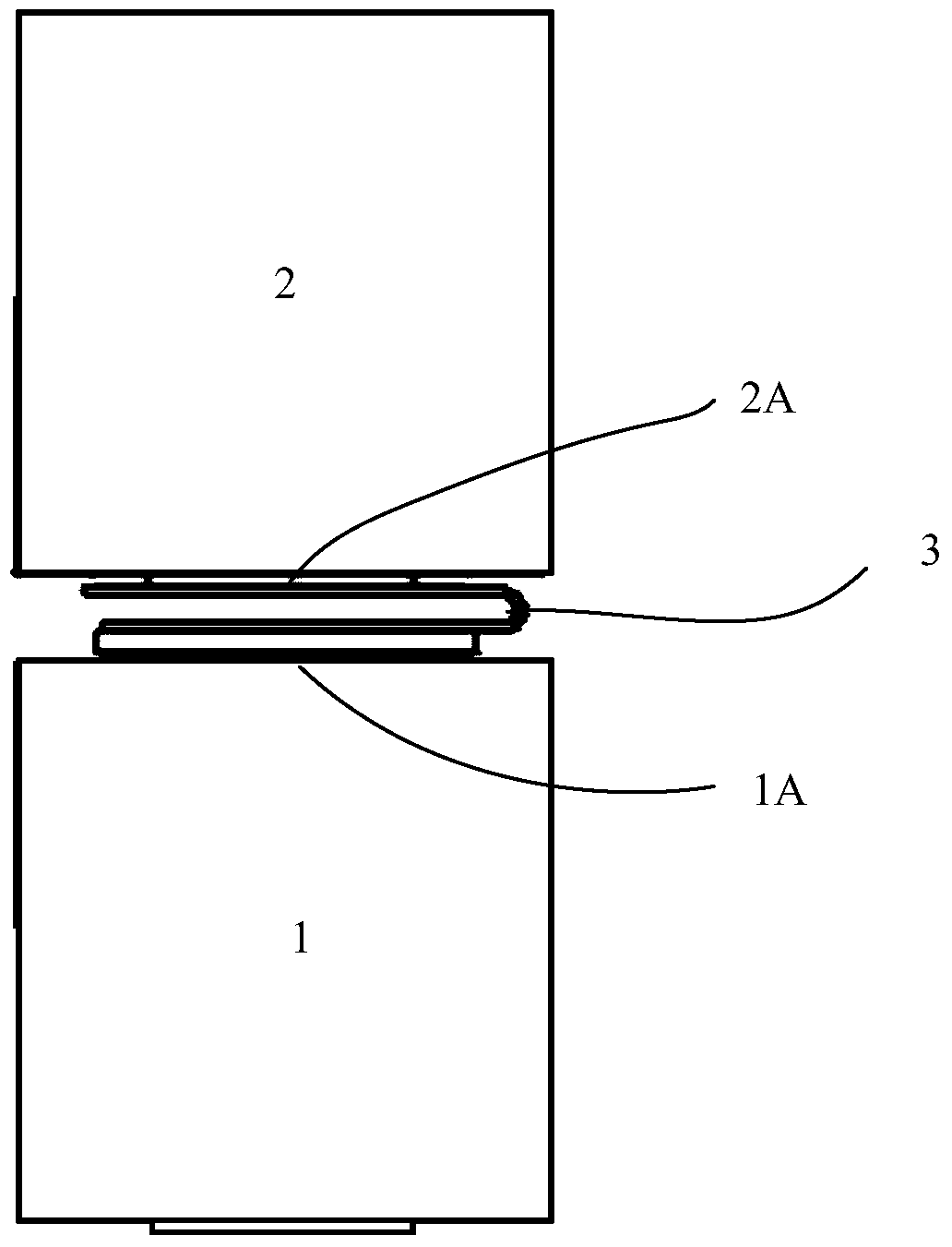
[0062] Figure 2A It is a top view showing the PTC device of one embodiment of the present invention. Figure 2B is a front view of the sealing plate assembly 1 .

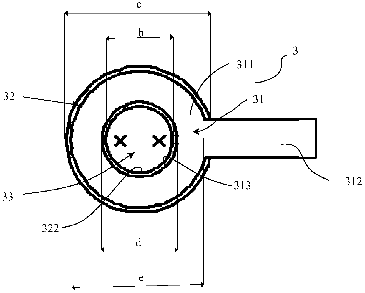
[0063] Figure 2A The PTC device 3 comprises an upper electrode layer 31, a PCT layer 32, and a lower electrode layer 33, which are stacked in order from top to bottom and bonded together.

[0064] When looking down on the PTC device 3, as Figure 2A As shown, the main body 311 of the uppermost electrode layer 31 is formed in an annular shape, and a tab 312 is formed extending radially outward from a part of its outer edge. The inner periphery of the main body 311 forms a window 313 for the upper electrode layer 31 to expose the PTC layer 32 and the lower electrode layer 33 which will be described later. The tab 312 is preferably formed in a strip shape. When the P...

Embodiment approach 2

[0080] Next, Embodiment 2 of the present invention will be described with reference to FIG. 5 . A detailed description of the points of the second embodiment that are the same as those of the first embodiment will be omitted, and only the points of difference will be described.

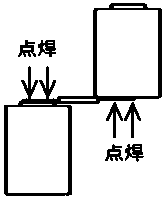
[0081] Such as Figure 5A As shown, the upper electrode layer 31 has a circular end portion 314 at the end of the lug 312 opposite to the main body 311 , and the diameter of the end portion 314 is f. Preferably, the diameter f of the end portion 314 is greater than the inner diameter b of the PTC layer 32 . Here, the end portion 314 is used as a site for spot welding

[0082] This is because, when the end 314 is spot-welded to the battery 2, and the battery 2 is rotated 180 degrees counterclockwise to the top of the battery 1, the end 314 is connected with the window 313 and the PTC layer from the main body 311 of the upper electrode layer 31. The lower electrode layer 33 exposed by the window 312 ...

Embodiment approach 3

[0086] refer to Figure 6A , Figure 6B The PTC device 5 of the third embodiment will be described.

[0087] The PTC device 5 also has an upper electrode layer 51 , a PTC layer 52 and a lower electrode layer 53 . A strip-shaped tab 512 extends radially outward from the edge of the main body 511 of the upper electrode layer 51 .

[0088] The main body 511 of the upper electrode layer 51, the PTC layer 52, and the lower electrode layer 53 are all formed in a circular shape, and the diameter of the lower electrode layer 53 is larger than the diameter of the PTC layer 52, and the diameter of the PCT layer 52 is larger than that of the main body 511 of the upper electrode layer 51. diameter. Hence, from Figure 6A From the top view of the PTC device 5, the PTC layer 52 is exposed from the outer peripheral edge of the main body 511 of the upper electrode layer 51, and the lower electrode layer 53 is exposed from the outer peripheral edge of the PTC layer 52.

[0089] Here, the ...


PUM


Abstract

The invention provides a PTC device and a battery pack, wherein the PTC device comprises a PTC layer, an upper electrode layer formed on the upper surface of the PTC layer, and a lower electrode layer formed on the lower surface of the PTC layer; the upper electrode layer is electrically connected with a terminal of one battery in the battery pack, the lower electrode layer is electrically connected with a terminal of another battery in the battery pack, windows are respectively formed on the PTC layer and the upper electrode layer, the lower electrode layer is exposed towards one side of the upper electrode layer through the window of the PTC layer and the window of the upper electrode layer, and an integrally formed electrode lug is formed on the upper electrode layer, extends to the outer side from the edge of the main body of the upper electrode layer, and is used for being electrically connected with the terminal of one battery.

Description

technical field [0001] The invention relates to a PTC device used in a battery pack and a battery pack equipped with the device. Background technique [0002] A battery pack with multiple single cells is increasingly used in electronic equipment such as cameras, video cameras, computers, etc., and the single cells mostly use secondary batteries capable of charging and discharging. In the prior art, in order to protect the battery pack from overcurrent and overtemperature generated during repeated charging and discharging, circuit protection devices are used to connect individual cells. [0003] As the above-mentioned circuit protection device, a PTC device (thermistor device) is generally used. In the PTC device, for example, conductive particles such as carbon black and metal particles are dispersed in a polymer, and the obtained PTC composition is formed into a sheet to form a PTC device, and a metal electrode such as a metal foil is attached to the surface and the back o...

Claims


Application Information

Patent Timeline
Patent Type & Authority Patents(China)
IPC IPC(8): H01C7/02H01M10/42H01M2/34H01M2/20H01M2/26
CPCY02E60/10
Inventor 巩桎茹聂秋根
Owner PANASONIC ENERGY WUXI
Why Eureka
Try Eureka