Folding plug-in valve hall grounding switch

An earthing switch and plug-in technology, applied in the field of earthing switches for high-end DC valve halls, can solve the problems of reducing the reliability of the switch, affecting the accuracy of opening and closing, and the length of the grounding conductive rod, so as to improve the stability and service life, Conducive to smooth movement and long opening and closing distance

Active Publication Date: 2018-10-02
STATE GRID CORP OF CHINA +1
View PDF9 Cites 0 Cited by
  • Summary
  • Abstract
  • Description
  • Claims
  • Application Information

AI Technical Summary

Problems solved by technology

However, the problem of the straight swing structure switch is that the site layout of the large fracture distance, the grounding conductive rod is too long, and there will be obvious bending deformation phenomenon due to its own weight. When the operating mechanism operates the grounding conductive rod, it needs to overcome the gravity of the conductive rod. The required operating force is large, which affects the normal opening and closing of the switch; when the distance of the static contact to the ground is much smaller than the distance to the wall, the straight structure will not be able to meet the engineering requirements; During the process, there will be obvious shaking, which will cause great uncertainty to the equipment; in addition, after the switch without auxiliary support is stretched, the long-running 15-meter horizontal conductive pipe will shift downward under the action of its own weight , affecting the accuracy of opening and closing, greatly reducing the reliability of the switch

Method used


Image

  • Folding plug-in valve hall grounding switch
  • Folding plug-in valve hall grounding switch
  • Folding plug-in valve hall grounding switch

Examples


Embodiment Construction

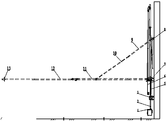
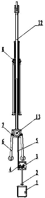
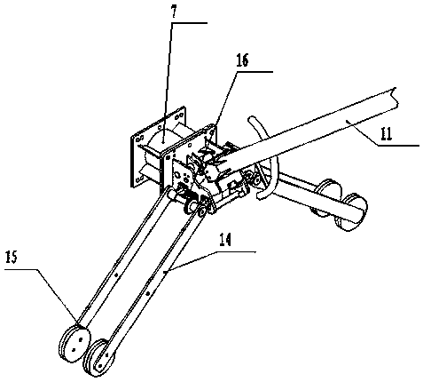
[0023] A folding plug-in valve hall grounding switch as shown in the attached figure, it includes an operating mechanism 1, a vertical transmission rod 2, a reversing box 3, a transmission connecting rod 5, a base I7, a base II8, a conductive tube, a static contact, The reversing box 3, the base I7 and the base II8 are all fixed on the wall of the valve hall, the operating mechanism 1 is connected to the reversing box 3 through the vertical transmission rod 2, the reversing box 3 is connected to the conductive tube through the transmission connecting rod 5, and the end of the conductive tube There is a moving contact 13 on the upper part, and the action of the conductive tube is in contact with the static contact. The device also includes a counterweight device for buffering and balancing the action of the conductive rod. The counterweight device is arranged on both sides of the base I7. The counterweight device includes a bevel gear set , the counterweight plate 14 and the cou...


PUM


Abstract

The invention discloses a folding plug-in type valve hall grounding switch. The folding plug-in type valve hall grounding switch comprises an operating mechanism, a vertical transmission rod, a reversing box, a transmission connection rod, a pedestal I, a pedestal II, a conductive tube and a static contact; the reversing box, the pedestal I and the pedestal II all are fixed on a wall of a valve hall; the operating mechanism is connected with the reversing box via the vertical transmission rod; the reversing box is connected with the conductive tube via the transmission connection rod; a moving contact is arranged on an end part of the conductive tube; the conductive tube, in an action, is in contact connection with the static contact; the folding plug-in type valve hall grounding switch further comprises a counterweight device for buffering and balancing the action of the conductive rod; the counterweight device is arranged at the two sides of the pedestal I; when a lower tube of the conductive tube moves, a rotating shaft drives counterweight plates via bevel gears to act together; when the switch is closed, the counterweight plates are unfolded towards a horizontal direction; and when the switch is opened, the counterweight plates are folded vertically and downwardly. Compared with the existing grounding switches, the folding plug-in type valve hall grounding switch has the characteristics of large fracture distance, small operating force, small closing impact, stable and reliable action, good dynamic thermal stability and long service life.

Description

technical field [0001] The invention relates to the field of DC power transmission and transformation equipment, in particular to a grounding switch for a high-end DC valve hall. Background technique [0002] Ultra-high voltage power transmission has the inherent characteristics of large capacity, long distance, low loss, and less land occupation. It is a power transmission method in line with my country's basic national conditions. The adoption of ultra-high voltage transmission technology can realize the optimal allocation of resources in a wider range, promote the efficient development and utilization of energy in my country, improve the atmospheric environment, and promote the sustainable development of economy and society. [0003] The Changji-Guquan ±1100 kV UHV DC transmission project is currently the UHV transmission project with the highest voltage level, the largest transmission capacity, the longest transmission distance and the most advanced technology in the wor...

Claims


Application Information

Patent Timeline
Patent Type & Authority Patents(China)
IPC IPC(8): H01H31/02
CPCH01H31/02H01H31/026
Inventor 郭贤珊韩长庚付颖乐波祝全乐李善成卢立富闫士忠
Owner STATE GRID CORP OF CHINA
Why Eureka
Try Eureka