Non-polar field bus system and realization method

A field bus, non-polarity technology, applied in the direction of total factory control, total factory control, electrical program control, etc., can solve the problems of long preparation period, high application cost, damaged interface, etc., and achieve simple construction wiring and strong anti-interference ability , The effect of reducing the project cost

Inactive Publication Date: 2010-08-25
NANJING UNIV OF AERONAUTICS & ASTRONAUTICS +1
View PDF5 Cites 16 Cited by
  • Summary
  • Abstract
  • Description
  • Claims
  • Application Information

AI Technical Summary

Problems solved by technology

When the common mode voltage of the network line exceeds this range, it will affect the stability and reliability of the communication, and even damage the interface
(2) EMI problem, the common mode part in the output signal of the sending driver needs a return path, if there is no low-impedance return path (signal ground), it will return to the source in the form of radiation, and the entire bus will be like a huge The antenna radiates electromagnetic waves outward
Therefore, the structure of the RS485 bus is simple, but it is easy to cause the instability of the automatic control system in the application, and there is no safeguard measure such as short-circuit detection inside, thus affecting the normal operation of the automatic control system
[0004] For large-scale bus systems such as CAN bus, PROFIBUS bus, and LONWORKS bus, the bus structure design is more complicated, the application cost is expensive, the preparation period is longer, and the bus cables are polarized, which makes wiring construction inconvenient. The application of small and medium-sized automatic control systems that actually require fieldbus has caused great inconvenience
In view of technical and economic reasons, the popularization and application of these fieldbuses in the actual automatic control system has been limited to a certain extent.

Method used


Image

  • Non-polar field bus system and realization method
  • Non-polar field bus system and realization method
  • Non-polar field bus system and realization method

Examples


Embodiment Construction

[0029] The specific implementation steps of the field bus system proposed by the present invention will be further described below in combination with specific diagrams.

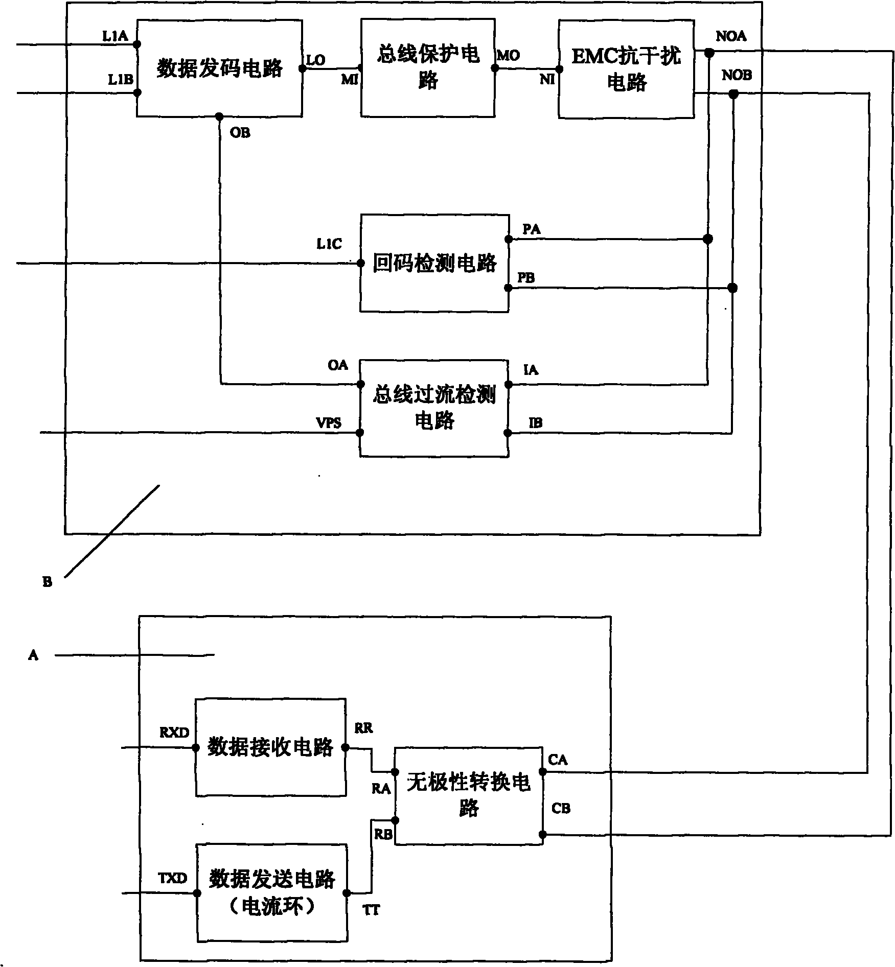
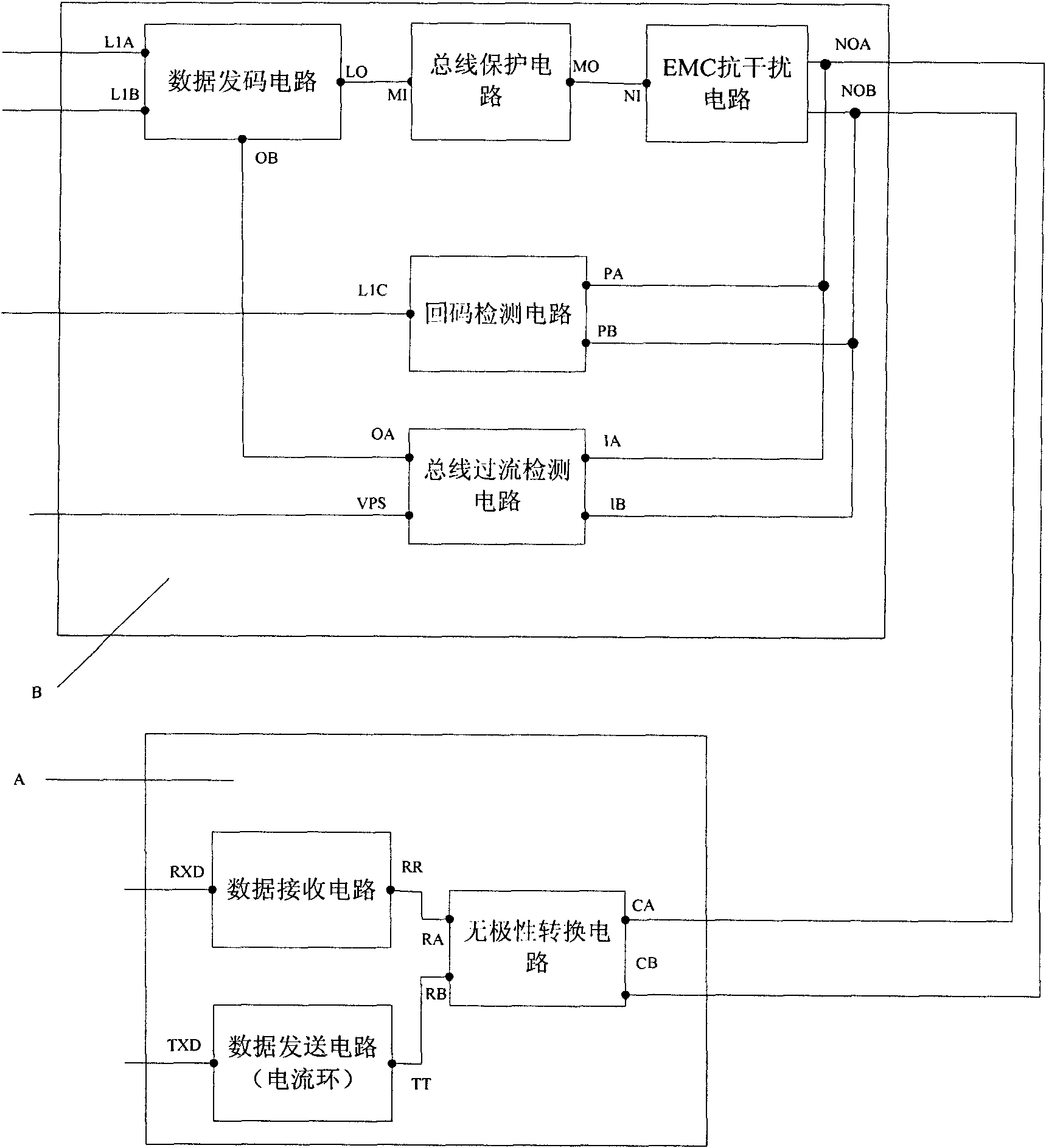
[0030]Figure 1 is a structural diagram of the non-polarity fieldbus system, including the master station DDC controller communication interface module and the slave station node controller communication interface module. The DDC controller communication interface module is composed of a data sending circuit, a bus protection circuit, an EMC anti-interference circuit, a return code detection circuit and a bus overcurrent detection circuit; the output terminal LO of the data sending circuit is connected to the input terminal of the bus protection circuit MI is connected, the output terminal MO of the bus protection circuit is connected to the input terminal NI of the EMC anti-interference circuit, the first output terminal NOA of the EMC anti-interference circuit is connected to the first non-polar cable; the s...


PUM


Abstract

The invention relates to a non-polar field bus system and a realization method, belonging to the field of field buses. The field bus system structurally comprises a master station DDC controller communication interface module and a slave station node controller communication interface module. The master station DDC controller communication interface module is formed by a data code sending circuit, a bus protection circuit, an EMC anti-interference circuit, a return code detection circuit and a bus overcurrent detection circuit. The slave station node controller communication interface module is formed by a data receiving circuit, a data transmitting circuit and a non-polar conversion circuit. The invention has the advantages that the structure of the field bus system is relatively simple and reasonable, the two buses are of non-polar design and the wiring construction is convenient.

Description

Technical field [0001] The invention relates to a field bus technology, in particular to a nonpolar field bus system and a realization method. It belongs to field bus system field and is used in automatic control system. Background technique [0002] Fieldbus refers to a data bus for digital, serial, multipoint communication between field devices installed in a manufacturing or process area and automatic devices in a control room. Fieldbus technology puts special-purpose microprocessors into traditional measurement and control instruments, so that they each have digital computing and digital communication capabilities, and uses twisted-pair wires that can be easily connected as buses to connect multiple measurement and control instruments into a network. System, and according to the open and standardized communication protocol, realize data transmission and information exchange between multiple microcomputerized measurement and control equipment located on the site and betw...

Claims


Application Information

Patent Timeline
Patent Type & Authority Applications(China)
IPC IPC(8): G05B19/418
CPCY02P90/02
Inventor 徐键张臣刘鑫涛徐迎辉毛凌韩舜
Owner NANJING UNIV OF AERONAUTICS & ASTRONAUTICS
Why Eureka
Try Eureka