Pouring and packaging type LED anti-explosion light source module and anti-explosion lamp

A light source module and encapsulation technology, which is applied in electric light sources, lighting and heating equipment, lighting devices, etc., can solve the problems of high shell cost, limit the application range of LED explosion-proof lamps, and low explosion-proof performance, and reach the application range Expansion, improvement of explosion-proof performance and safety, flexible use effect

Active Publication Date: 2017-05-10
邵泽渝 +1
View PDF6 Cites 3 Cited by
  • Summary
  • Abstract
  • Description
  • Claims
  • Application Information

AI Technical Summary

Problems solved by technology

However, the current common LED explosion-proof lamps continue the design scheme of traditional lamps in terms of explosion-proof principles. The explosion-proof requirements can only be met through the thick and heavy shell, the wide explosion-proof surface and the cooperation of the whole lamp and various parts. The cost of the shell is high, and the explosion-proof performance is low, which limits the application range of LED explosion-proof lamps.

Method used


Image

  • Pouring and packaging type LED anti-explosion light source module and anti-explosion lamp
  • Pouring and packaging type LED anti-explosion light source module and anti-explosion lamp
  • Pouring and packaging type LED anti-explosion light source module and anti-explosion lamp

Examples


Embodiment Construction

[0031] The following will clearly and completely describe the technical solutions in the embodiments of the present invention with reference to the accompanying drawings in the embodiments of the present invention. Obviously, the described embodiments are only some of the embodiments of the present invention, not all of them. Based on the embodiments of the present invention, all other embodiments obtained by persons of ordinary skill in the art without creative efforts fall within the protection scope of the present invention.

[0032] It should be noted that if there is a directional indication (such as up, down, left, right, front, back...) in the embodiment of the present invention, the directional indication is only used to explain the position in a certain posture (as shown in the accompanying drawing). If the specific posture changes, the directional indication will also change accordingly.

[0033] In addition, if there are descriptions involving "first", "second" and ...


PUM

PropertyMeasurementUnit
Volume resistivityaaaaaaaaaa
Dielectric strengthaaaaaaaaaa
Thicknessaaaaaaaaaa

Abstract

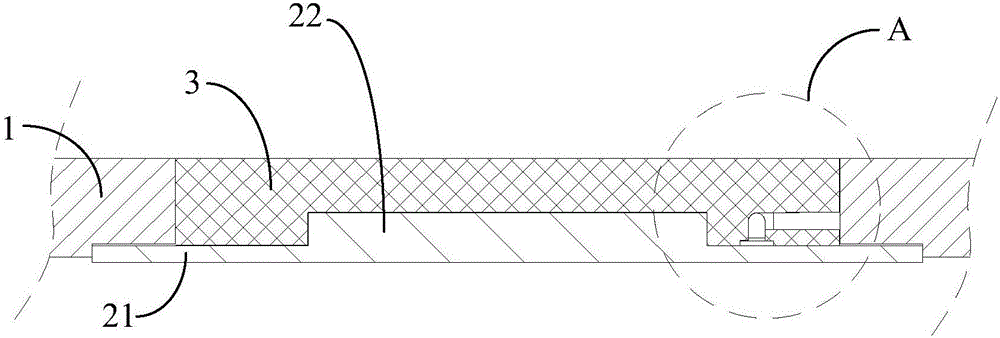
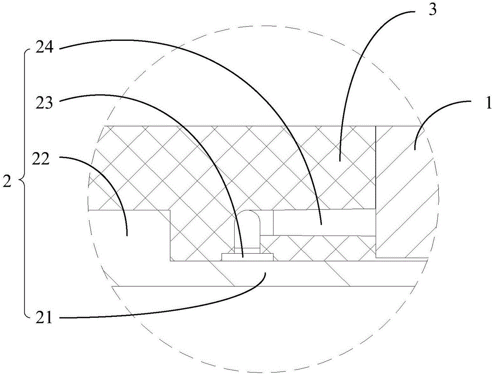
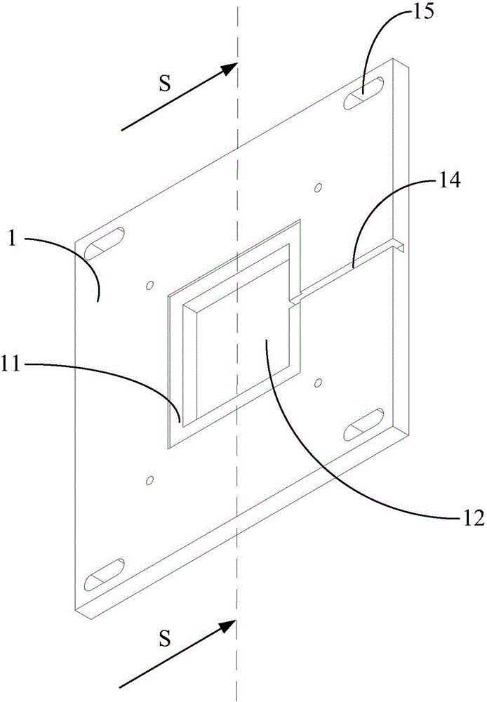
The invention discloses a pouring and packaging type LED anti-explosion light source module and an anti-explosion lamp. The pouring and packaging type LED anti-explosion light source module comprises a mounting board, a light source assembly and an anti-explosion packaging adhesive; a mounting groove is formed in the back surface of the mounting board; pouring and packaging holes which run through to the front surface of the mounting board are formed in the bottom wall of the mounting groove; the light source assembly comprises a light source substrate and an LED chip fixedly arranged on the front surface of the light source substrate; a bonding pad electrically connected with the LED chip is fixedly arranged on the periphery of the LED chip on the light source substrate; the light source substrate is adaptively clamped in the mounting groove, and connected with the mounting board in a sealing manner; the LED chip and the bonding pad are both positioned in the pouring and packaging holes; the pouring and packaging holes are formed in the front surface of the light source substrate in a surrounding manner to form a pouring and packaging cavity; and the pouring and packaging cavity is filled with the anti-explosion packaging adhesive. By virtue of the technical scheme, the anti-explosion performance of the LED anti-explosion lamp is improved, so that the applicable range of the LED anti-explosion lamp is wider.

Description

technical field [0001] The invention relates to the technical field of explosion-proof lighting, in particular to a potting-type LED explosion-proof light source module and an explosion-proof lamp. Background technique [0002] At present, explosion-proof lighting fixtures are required in many places such as coal mines, petroleum, chemical industry, ships and offshore platforms. Compared with traditional high-pressure sodium lamps, metal halide lamps, and incandescent light sources, LED light sources have been widely used in the field of explosion-proof lighting technology in recent years because of their long service life and energy-saving advantages. However, the current common LED explosion-proof lamps continue the design scheme of traditional lamps in terms of explosion-proof principles. The explosion-proof requirements can only be met through the thick and heavy casing, the wide explosion-proof surface and the cooperation of the whole lamp and various parts. The cost o...

Claims


Application Information

Patent Timeline
IPC IPC(8): H01L33/52H01L33/56H01L33/62F21S6/00
CPCF21S6/00H01L33/52H01L33/56H01L33/62
Inventor 戴兴建吴伟超陶尊伍邵泽渝
Owner 邵泽渝
Why Eureka
Try Eureka