
Novel cable erecting hook

A new type of cable technology, which is applied in the field of new cable erection hooks, can solve the problems of inapplicable cable hooks, difficult construction, and large vertical height, so as to facilitate installation operations, improve integration, and avoid shaking up and down.

Inactive Publication Date: 2017-05-10
LINGBAO CITY JINYUAN MINING
View PDF7 Cites 0 Cited by
  • Summary
  • Abstract
  • Description
  • Claims
  • Application Information

AI Technical Summary

Problems solved by technology

[0002] At present, the traditional cable hooks we use, due to their structural limitations, generally use steel strands to be erected in advance, and then use artificial climbing methods to support the power cables on the cable hooks and clamp the cable hooks on the steel strands. Or when the erection height is small, it has the advantages of convenient and beautiful construction; but in the actual construction process of power cable erection at high altitude, such as in mountainous or ravine construction sites, the pre-erected steel strands have a large span and a large vertical height from the ground. The construction of cable hooks by artificial climbing method has great construction difficulty and unsafe factors, while traditional cable hooks are not suitable for cable erection by sliding traction

Method used


Image

  • Novel cable erecting hook
  • Novel cable erecting hook
  • Novel cable erecting hook

Examples


Embodiment Construction

[0025] The specific implementation manners of the present invention will be described in detail below in conjunction with the accompanying drawings.

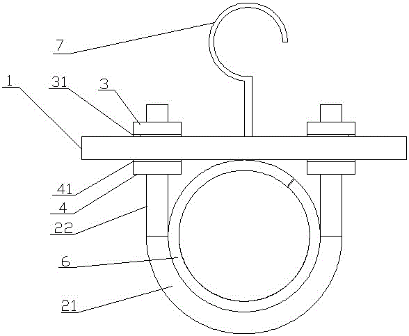
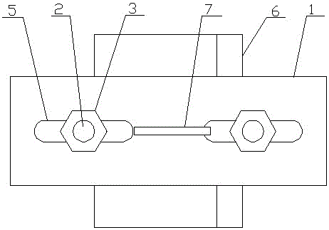
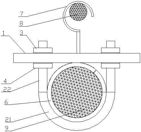
[0026] Such as figure 1 with figure 2 As shown, a novel cable erection hook of the present invention includes a mounting plate 1, a U-shaped clip 2 and a hook 7, and the U-shaped clip 2 is connected tangentially to the semicircular arc-shaped polished rod portion 21 and two respectively. The two screw parts 22 of the U-shaped clip 2 pass through the mounting plate 1 upwards, and the upper side of the screw part 22 is located on the upper side of the mounting plate 1. The part 22 is located at the lower side of the mounting plate 1 and is equipped with the lower lock nut 4; the mounting plate 1 is correspondingly provided with two mounting holes 5 for the screw part 22 of the U-shaped clip 2 to pass through, and the screw part 22 is in the corresponding The mounting holes 5 are in sliding fit with the mounting plate 1. The U-...


PUM


Abstract

The invention discloses a novel cable erecting hook. The novel cable erecting hook comprises a mounting plate, a U-shaped clamping piece and a hook, wherein the U-shaped clamping piece consists of a polished rod part in the shape of a semi-circular arc and two screw parts tangentially connected to two ends of the semi-circular arc respectively; the two screw parts of the U-shaped clamping piece pass through the mounting plate upwards, upper locking nuts are arranged at the positions, on the upper side of the mounting plate, of the screw parts in a matched manner, and lower locking nuts are arranged at the positions, on the lower side of the mounting plate, of the screw parts in the matched manner; two mounting holes for the screw parts of the U-shaped clamping piece to pass through are correspondingly formed in the mounting plate, and the screw parts are in sliding fit with the mounting plate at the positions of the corresponding mounting holes; the hook is arranged above the mounting plate, the hook is fixedly connected with the mounting plate, and the fixed connecting point of the hook and the mounting plate is positioned at the middle position between the two mounting holes; and a protective layer is arranged inside the polished rod part of the U-shaped clamping piece. The novel cable erecting hook is simple in structure and convenient and quick in construction, and the efficiency of cable construction is improved.

Description

technical field [0001] The invention relates to the technical field of cable construction, in particular to a novel cable erection hook. Background technique [0002] At present, the traditional cable hooks we use, due to their structural limitations, generally use steel strands to be erected in advance, and then use artificial climbing methods to support the power cables on the cable hooks and clamp the cable hooks on the steel strands. Or when the erection height is small, it has the advantages of convenient and beautiful construction; but in the actual construction process of power cable erection at high altitude, such as in mountainous or ravine construction sites, the pre-erected steel strands have a large span and a large vertical height from the ground. The construction of cable hooks by artificial climbing method has great construction difficulty and unsafe factors, while the traditional cable hooks are not suitable for cable erection by sliding traction. Contents ...

Claims


Application Information

Patent Timeline
IPC IPC(8): H02G7/06
CPCH02G7/06
Inventor 张文华饶红斌王育和李东齐方冠冠李晓飞杨伟明范磊芬
Owner LINGBAO CITY JINYUAN MINING
Learn More