Automatic load control terminal switching device of dual-power-supply user

A load control, dual power supply technology, applied in circuit devices, electrical components, AC network circuits, etc., can solve the problem of increasing enterprise operation and maintenance costs and safety risks of on-site operations, affecting the development of remote cost control load management, and not suitable for large-scale installations application and other issues, to achieve the effect of facilitating large-scale application, avoiding terminal outage and simple structure

Inactive Publication Date: 2017-05-10
YANTAI POWER SUPPLY COMPANY OF STATE GRID SHANDONG ELECTRIC POWER +1
View PDF4 Cites 1 Cited by
  • Summary
  • Abstract
  • Description
  • Claims
  • Application Information

AI Technical Summary

Problems solved by technology

The trouble that this power supply method brings to the power consumption information collection system is that the load control terminal is only connected to the PT of the user's main power supply. At the same time as the decline, it also affects the development of other businesses such as remote fee control and load management. On-site operation and maintenance also increases the company's operation and maintenance costs and on-site operation safety risks
[0005] Most of the existing automatic switching devices for user load control terminals are large in size, cumbersome to install, and high in cost, and are not suitable for large-scale installation and application. Therefore, it is urgent to study an automatic switching device for load control terminals that can meet various work requirements

Method used


Image

  • Automatic load control terminal switching device of dual-power-supply user
  • Automatic load control terminal switching device of dual-power-supply user

Examples


Embodiment

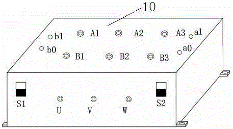
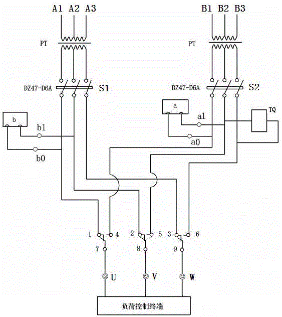
[0019] Embodiment: a dual power supply user load control terminal automatic switching device (see figure 1 , figure 2 ), which includes a main body 10, and the main body 10 is provided with the main power supply terminal A1, the main power supply terminal A2, the main power supply terminal A3, the auxiliary power supply terminal B1, the auxiliary power supply terminal B2, the auxiliary power supply Terminal B3, connection terminals a1 and a0 of the communication module of electric energy meter A, connection terminals b1 and b0 of the communication module of electric energy meter B, the front end of the main body 10 is provided with U-phase output terminal, V-phase output terminal, W-phase output terminal, and main power supply circuit switch S1, auxiliary power supply circuit switch S2, the main power supply terminal A1 is connected to the main power supply voltage secondary side a, the main power supply terminal A2 is connected to the main power supply voltage secondary side...


PUM


Abstract

The invention discloses an automatic load control terminal switching device of a dual-power-supply user. A main power supply terminal arranged at a main body (10) is connected with a main contact of a relay by a voltage transformer PT and a main supply circuit switch S1 and an auxiliary power supply terminal is connected with an auxiliary contact of the relay by the voltage transformer PT and an auxiliary circuit switch S2; the relay is connected with a voltage output port connected with a load control terminal; and a tripping coil TQ is connected with the auxiliary circuit switch S2 and the relay. An electric energy meter A communication module a is connected with the auxiliary circuit switch S2 and the relay; an electric energy meter B communication module b is connected with the main supply circuit switch S1 and the relay. The automatic load control terminal switching device has advantages of simple structure, low cost, low power consumption, convenience in installation, greatly reduced maintenance staff workload, saved enterprise costs and reduced field work security risk.

Description

[0001] Technical field: [0002] The invention relates to an automatic switching device for dual power supply user load control terminals, which belongs to the technical field of electric energy collection, operation and maintenance. [0003] Background technique: [0004] "Full coverage, full collection, full cost control" is the construction goal of the State Grid Corporation's electricity consumption information collection system. The load control terminal is used for real-time collection and monitoring of electricity consumption information for users. The load control terminal is divided into three-phase three-wire and three-phase Four-wire and two-wire, dual-power users mostly use three-phase three-wire acquisition terminals with a working voltage of 3*100V. With the improvement of power supply reliability requirements, the number of customers will continue to increase. The troubles brought by this power supply method to the power consumption information collection system ...

Claims


Application Information

Patent Timeline
Patent Type & Authority Applications(China)
IPC IPC(8): H02J3/00
CPCH02J3/005
Inventor 万召杰宋春辉廖烽然于林卉王炫丹于洨王俊涛于秀梅曹勇宋书强马传波
Owner YANTAI POWER SUPPLY COMPANY OF STATE GRID SHANDONG ELECTRIC POWER
Why Eureka
Try Eureka