Electric energy circulation equipment and method

A technology for recycling equipment and electric energy, applied in the direction of motors, electromechanical devices, electric vehicles, etc., can solve the problems of poor battery life and insufficient power to reach the destination.

Pending Publication Date: 2017-05-10
朱冰
View PDF0 Cites 0 Cited by
  • Summary
  • Abstract
  • Description
  • Claims
  • Application Information

AI Technical Summary

Problems solved by technology

The battery life is poor, and it must be used for external charging every day. If the battery is exhausted, it cannot be operated, and it is easy to fail to reach the destination due to insufficient power on the road.

Method used


Image

  • Electric energy circulation equipment and method
  • Electric energy circulation equipment and method

Examples


Embodiment 1

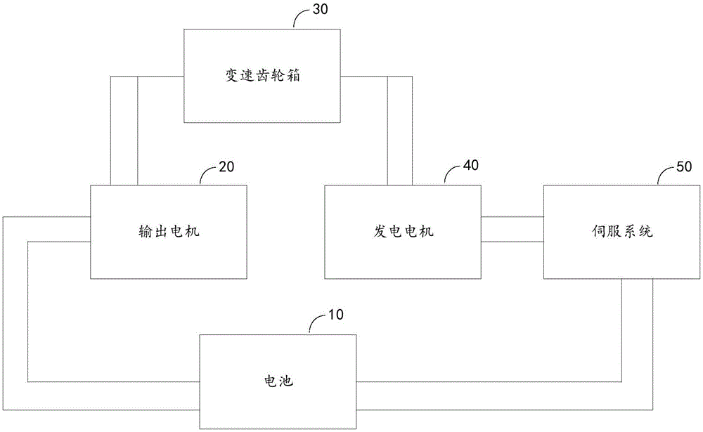
[0035] figure 1 It is a schematic structural diagram of the electric energy recycling equipment provided by Embodiment 1 of the present invention.

[0036] refer to figure 1 , the power cycle equipment, including: a battery 10, an output motor 20, a transmission gearbox 30, a generator motor 40 and a servo system 50;

[0037] The output end of the generator motor 40 is connected with the input end of the servo system 50, the output end of the servo system 50 is connected with the input end of the battery 10, the output end of the battery 10 is connected with the input end of the output motor 20, and the output end of the output motor 20 The main shaft of the main shaft and the generator motor 40 are respectively connected with the transmission gearbox 30;

[0038] When the target object starts, the first electric energy released by the battery 10 connects the output motor 20, and the main shaft of the output motor 20 rotates the speed change gearbox 30, so that the speed cha...

Embodiment 2

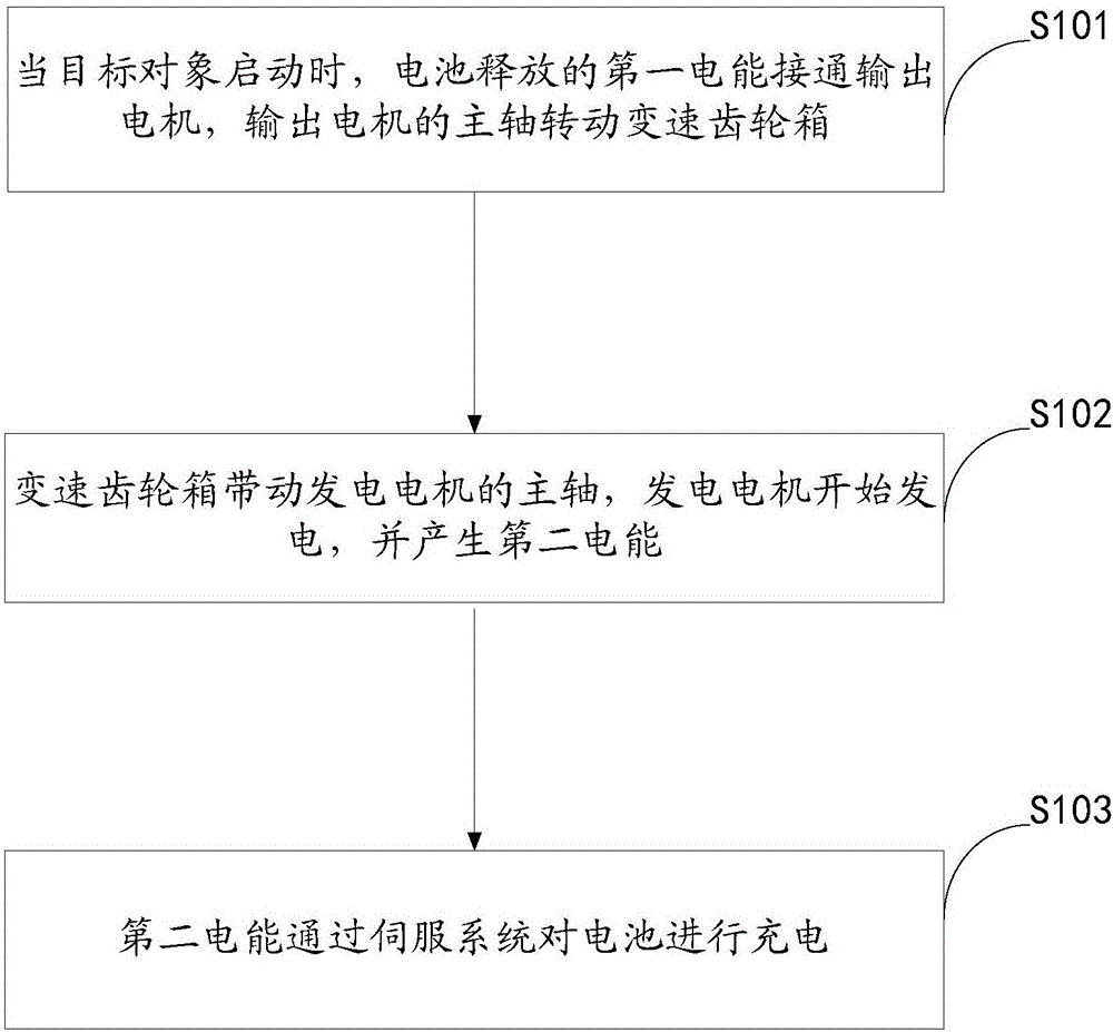
[0065] figure 2 It is a flow chart of the electric energy recycling method provided by Embodiment 2 of the present invention.

[0066] refer to figure 2 , the method includes the steps of:

[0067] Step S101, when the target object is started, the first electric energy released by the battery is connected to the output motor, and the main shaft of the output motor rotates the transmission gearbox;

[0068] Specifically, the target objects here can be regarded as electric vehicles, electric motorcycles, etc. that apply the electric energy cycle equipment;

[0069] Wherein, when the target object is started, the battery releases the first electric energy, the input circuit of the output motor is powered on, the output motor is connected, and starts to work, and the electric spindle of the output motor rotates the transmission gearbox;

[0070] Step S102, the transmission gearbox drives the main shaft of the generator motor, and the generator motor starts to generate electri...


PUM


Abstract

The invention provides electric energy circulation equipment and method, and relates to the technical field of environmental protection and energy conservation. The electric energy circulation equipment comprises a battery, an output motor, a speed change gear box, a power generation motor and a servo system; when a target object is started, the output motor is switched on by first electric energy released by the battery; a main shaft of the output motor rotates the speed change gear box to enable the speed change gear box to drive a main shaft of the power generation motor, and then the power generation motor begins to generate electricity and generates second electric energy; and the battery is charged by the second electric energy through the servo system. Therefore, the disadvantage that an electric vehicle needs external charging is relieved, and the purpose of permanent endurance is achieved.

Description

technical field [0001] The invention relates to the technical field of environmental protection and energy saving, in particular to electric energy cycle equipment and methods. Background technique [0002] Energy saving, environmental protection and safety are the three major themes of automotive technology in the world today, among which energy saving technology is the key to the development of future automotive technology. Nowadays, electric vehicles have become an important trend in the development of energy-saving vehicles due to their significant advantages such as high energy efficiency, no pollution, low noise, simple structure, and convenient maintenance. But as we all know, current electric vehicles still have many shortcomings. [0003] Current electric motorcycles and electric cars all need external charging to use. The battery life is poor, and it must be used for external charging every day. If the battery power is exhausted, it cannot be operated, and it is ...

Claims


Application Information

Patent Timeline
Patent Type & Authority Applications(China)
IPC IPC(8): H02K53/00B60L11/18
CPCB60L50/50H02K53/00Y02T10/64Y02T10/70
Inventor 朱冰
Owner 朱冰
Why Eureka
Try Eureka