Wireless charging system for new energy automobile

A new energy vehicle and wireless charging technology, applied in the direction of electric vehicle charging technology, charging stations, electric vehicles, etc., can solve the problems of low power conversion efficiency, complex structure, troubles, etc., and achieve reduced maintenance costs, strong environmental adaptability, The effect of ease of use

Inactive Publication Date: 2020-06-16
赵洪超
View PDF5 Cites 0 Cited by
  • Summary
  • Abstract
  • Description
  • Claims
  • Application Information

AI Technical Summary

Problems solved by technology

At present, the charging method of new energy vehicles mainly relies on widely installed charging piles. However, charging piles cannot store a large amount of electric energy for the battery in a short period of time, and manual operation is required to connect the charger with the car battery. As a result, car charging not only takes up space , it’s inconvenient, and it’s a waste of time. If you’re running a long distance, the battery life will be insufficient, which will cause trouble for people; dynamic wireless charging is a technology that uses electromagnetic fields or electromagnetic waves for energy transfer. Inside the road surface, the secondary receiving coil is placed inside the car, and the electric energy is transmitted through the high-frequency magnetic field coupling, so that the new energy car can be charged while driving. Because it is completely insulated, it can avoid the risk of high-voltage electric shock, and its full seal can avoid short circuit and leakage Dangerous, can adapt to a variety of harsh environments and weather, it has no mechanical wear, maintenance-free, easy to automate operations, but the existing dynamic wireless charging system for new energy vehicles has low power conversion efficiency, complex structure, and high cost. A new energy vehicle wireless charging system

Method used


Image

  • Wireless charging system for new energy automobile
  • Wireless charging system for new energy automobile
  • Wireless charging system for new energy automobile

Examples


Embodiment Construction

[0013] A new energy vehicle wireless charging system of the present invention will be further described in detail below in conjunction with the accompanying drawings.

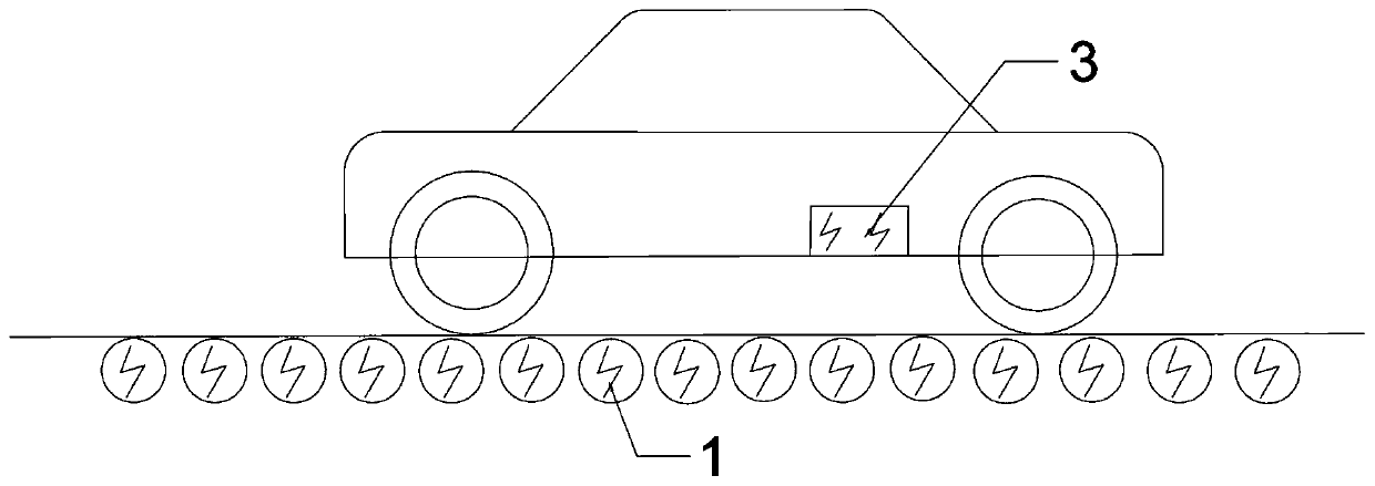
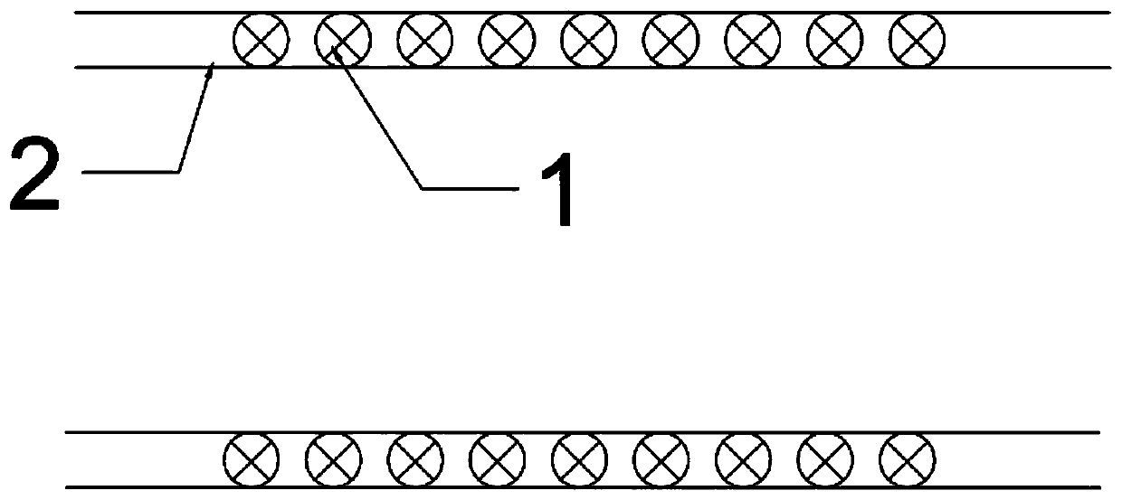
[0014] combined with Figure 1-3 , a wireless charging system for new energy vehicles, comprising a ground-side coupling coil 1, a power line 2 and a car-side coupling coil 3, the ground-side coupling coil 1 is arranged at the lower end of the road surface, and the power line 2 is arranged at the lower end of the road surface, so The coupling coil 1 at the ground end is connected to the power line 2;

[0015] The car end coupling coil 3 is arranged at the lower end of the car.

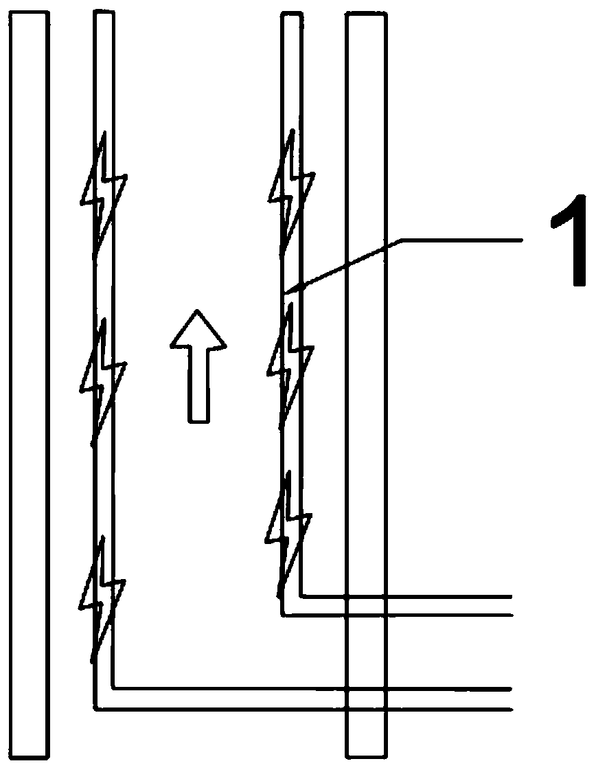
[0016] The ground coupling coils 1 are correspondingly provided with two rows.

[0017] There are two corresponding power cords 2 .

[0018] When the present invention is concretely implemented, at first the ground end coupling coil 1 and the power line 2 are laid on the road, and on the national, provincial and county roads, the gro...


PUM


Abstract

The invention discloses a new energy automobile wireless charging system, which comprises a ground end coupling coil, a power line and an automobile end coupling coil, and is characterized in that theground end coupling coil is arranged at the lower end of a road surface, the power line is arranged at the lower end of the road surface, and the ground end coupling coil is connected with the powerline; the automobile end coupling coil is arranged at the lower end of the automobile; compared with the prior art, a charging wire is omitted, the charging pile has the advantages of being easy to operate, high in safety, high in environment adaptability and the like, charging is achieved during road driving, permanent endurance of a new energy vehicle on a road is achieved, the damage probability is far lower than that of a wired charging pile, and therefore the maintenance cost can be greatly reduced.

Description

technical field [0001] The invention relates to a new energy vehicle, in particular to a wireless charging system for a new energy vehicle. Background technique [0002] my country's new energy vehicles are mainly hybrid vehicles and pure electric vehicles. The charging problem of these two types of vehicles has always been the main obstacle to the development of new energy vehicles. At present, the charging method of new energy vehicles mainly relies on widely installed charging piles. However, charging piles cannot store a large amount of electric energy for the battery in a short period of time, and manual operation is required to connect the charger with the car battery. As a result, car charging not only takes up space , it’s inconvenient, and it’s a waste of time. If you’re running a long distance, the battery life will be insufficient, which will cause trouble for people; dynamic wireless charging is a technology that uses electromagnetic fields or electromagnetic wav...

Claims


Application Information

Patent Timeline
Patent Type & Authority Applications(China)
IPC IPC(8): B60L53/12H02J7/02H02J50/10
CPCB60L53/12H02J50/10Y02T10/70Y02T10/7072Y02T90/14
Inventor 赵洪超赵法勇
Owner 赵洪超
Why Eureka
Try Eureka