Device for producing composite optical element and method for producing composite optical element

A technology for optical components and manufacturing devices, applied in the directions of optical components, optical components, optics, etc., can solve the problems of large impact on optical performance, decreased optical performance, and large state impact of composite optical components.

Active Publication Date: 2017-05-10
OLYMPUS CORP
View PDF9 Cites 2 Cited by
  • Summary
  • Abstract
  • Description
  • Claims
  • Application Information

AI Technical Summary

Problems solved by technology

Therefore, the molten state and the solidified state have a great influence on the state of the first optical functional surface, and as a result, have a great influence on the optical performance of the composite optical element.
For example, when the first optical functional surface is deformed due to melting or joint unevenness occurs, the optical performance is degraded

Method used


Image

  • Device for producing composite optical element and method for producing composite optical element
  • Device for producing composite optical element and method for producing composite optical element
  • Device for producing composite optical element and method for producing composite optical element

Examples


no. 1 approach

[0035] [structure]

[0036] refer to Figure 1A , Figure 1B , figure 2 , image 3 , Figure 4 , Figure 5 , Image 6 , Figure 7 with Figure 8 The first embodiment will be described. In addition, in some drawings, illustration of some components is omitted for clarity of illustration.

[0037] [Compound Optical Element 10]

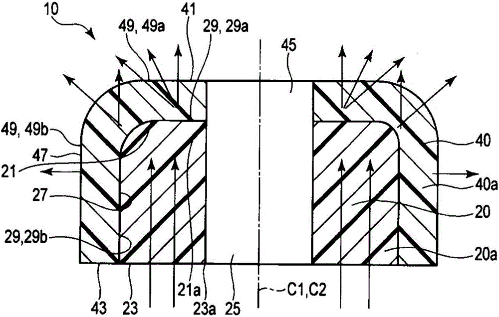
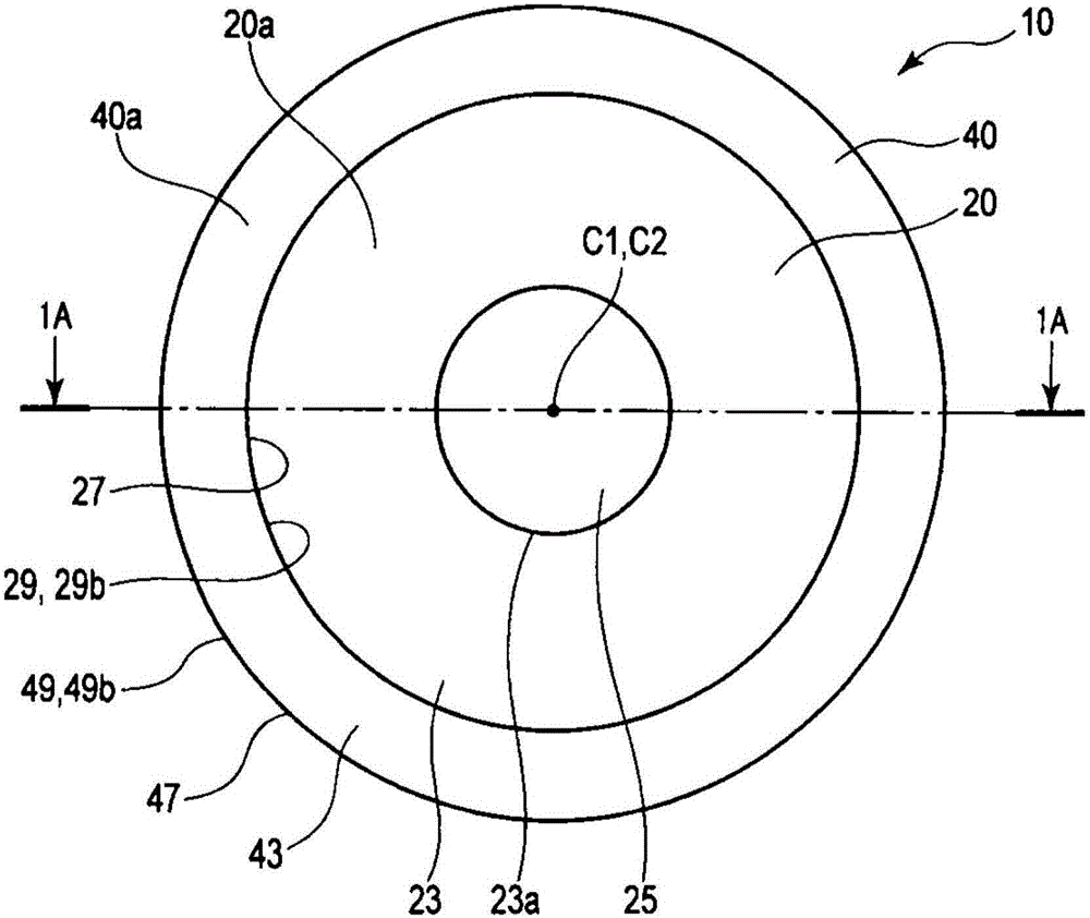
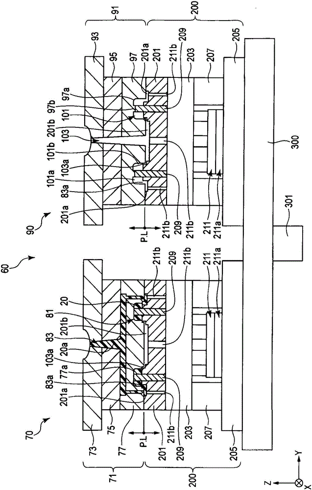
[0038] Such as Figure 1A with Figure 1B The shown composite optical element 10 is injection-molded using a manufacturing apparatus 60 described later. Such a composite optical element 10 includes an optical component such as a lens for illumination, for example.

[0039] The composite optical element 10 has: the first optical element part 20 as a primary molded product, which is molded using the first molding material 20a in the primary molding; and the second optical element part 40 as a secondary molded product, which is molded in the secondary molding In this process, the second molding material 40a is used for molding.

[0040] The fi...


PUM


Abstract

This device (60) for producing a composite optical element (10) comprises: a first cavity section (81) that molds, with a first molding material (20a) in a primary molding step, a first optical element section (20) having a first optical function surface (29) in a portion thereof; and a second cavity section (101) that molds, with a second molding material (40a) in a secondary molding step, a second optical element section (40) provided to the first optical element section (20) so as to cover the first optical function surface (29), the second cavity section molding a composite optical element (10) by integrating the second optical element section (40) with the first optical element section (20). The production device (60) has a second discharge opening section (103a) in which the discharge direction of the second molding material (40a) from a second supply path section (103) to the second cavity section (101) is along the first optical function surface (29).

Description

technical field [0001] The present invention relates to a manufacturing device of a compound optical element and a manufacturing method of the compound optical element. Background technique [0002] For example, Patent Document 1 discloses a molding method and a molding die for molding a composite optical element by two-color molding. This composite optical element is molded by joining two optical element parts to each other. [0003] In the composite optical element described above, the first optical element part is molded with a first meltable molding material in primary molding, and the second optical element part is molded with a second meltable molding material in secondary molding. The first optical element part has a first optical function surface arranged on the outer peripheral surface of the first optical element part. In secondary molding, the second optical element portion is integrated with the first optical element portion by covering and joining the first op...

Claims


Application Information

Patent Timeline
Patent Type & Authority Applications(China)
IPC IPC(8): B29C45/16G02B3/00B29L11/00
CPCB29C45/1635B29D11/00403B29L2011/00B29C2045/1637G02B3/06B29C45/16B29D11/00
Inventor 菊森一洋
Owner OLYMPUS CORP
Why Eureka
Try Eureka