Process and apparatus for decoking a hydrocarbon steam cracking furnace
A steam and pyrolysis furnace technology, which is applied in cracking, hydrocarbon oil treatment, non-catalytic thermal cracking, etc., can solve the problems of increasing pipeline thermal fatigue, leakage, pipeline thermal fatigue failure flanges, etc., and achieve the effect of reducing demand
- Summary
- Abstract
- Description
- Claims
- Application Information
AI Technical Summary
Problems solved by technology
Method used
Image

Examples
Embodiment 1
[0042] Embodiment 1 (comparison)
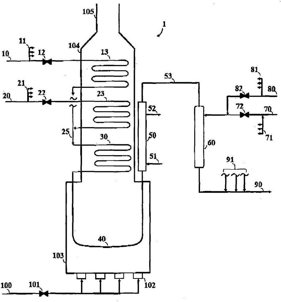
[0043] In this comparative example, using as figure 1system shown. Heavy gas oil may be fed through line 10 at a rate of 91 Mg / hr (200 klb / hr). Quench oil is supplied through line 70 at a rate of 182 Mg / hr (400 klb / hr) to cool the furnace effluent. When decoking, the temperature in effluent conduit 53 can reach 580°C (1075°F). Equipment (not shown) downstream of conduit 90 may be fabricated from carbon steel and designed to operate at temperatures below 449°C (840°F). Quench water may be injected through line 80 to cool the decoking effluent. Due to stratified flow and resulting variability in the previously discussed decoke effluent temperature measurement, the target effluent temperature was 315°C (600°F) obtained with a quench water flow rate of approximately 14 Mg / hr (31 klb / hr) .
[0044] Since the quench oil device 60 in the present embodiment is designed to flow the quench oil of 182Mg / hr (400klb / hr), when only the quench water o...
Embodiment 2
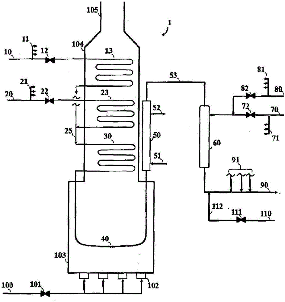
[0046] The same 91 Mg / hr (200 klb / hr) heavy gas oil feed used in Example 1 can be fed to a feed such as figure 2 In a similar furnace of construction as shown. Again, the quench unit 60 is designed for a quench oil flow of 182 Mg / hr (400 klb / hr). During decoking, instead of water, quench steam may be supplied through line 80 or through line 110, or both, to cool the decoking process effluent. Since the addition of quench steam does not result in stratified flow, the target effluent temperature can be raised to 427°C (800°F) (closer to the carbon steel temperature limit of 449°C (840°F)) and approximately 40Mg / hr ( 88klb / hr) quenched steam at medium pressure 188°C (370°F). The use of quench steam avoids the problems of stratification, mechanical fatigue and variable temperature control by eliminating the use of quench water.
Embodiment 3
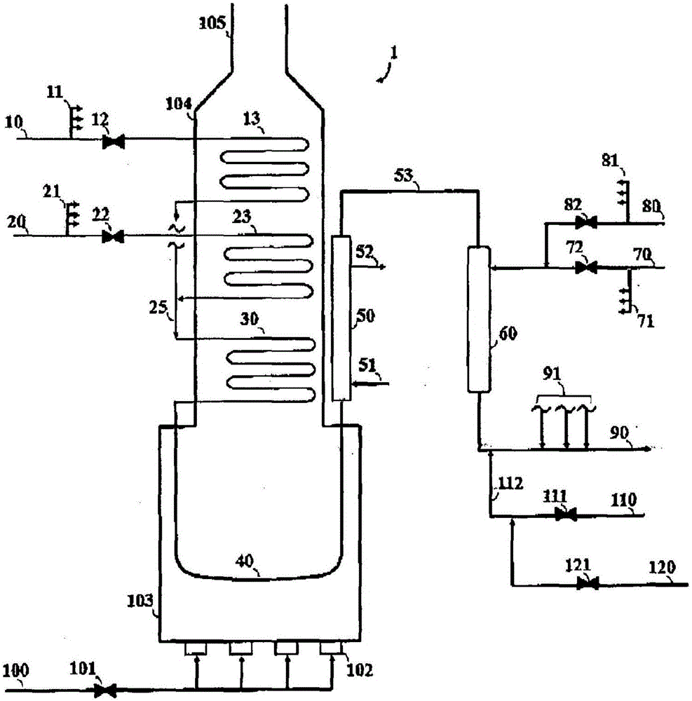
[0048] The same 91 Mg / hr (200 klb / hr) heavy gas oil feed used in Example 1 can be fed to a feed such as image 3 In a similar furnace of construction as shown. Again, quench unit 60 is designed for a quench oil flow of 182 Mg / hr (400 klb / hr). During decoking, instead of water, quench steam may be supplied through line 110 to cool the decoking process effluent. In order to minimize the rate of quench steam required, and thus reduce the velocity in the pipes (so as to reduce the rate of attrition), quench steam close to its saturation temperature can be used. Since the operating pressure of line 90 can be at about 0.82 atm gauge (12 psig) or less, the quench steam can be cooled to 121°C (250°F) (about 3.5°C above the quench steam saturation temperature) without adding to the Risk of adding excess water to char effluent. Use a composition consisting of approximately 1.3Mg / hr (3klb / hr) of desuperheated water (supplied through line 120) and approximately 32.7Mg / hr (72klb / hr) of ...
PUM
 Abstract
Description
Claims
Application Information
 - R&D
- Intellectual Property
- Life Sciences
- Materials
- Tech Scout
- Unparalleled Data Quality
- Higher Quality Content
- 60% Fewer Hallucinations
Browse by: Latest US Patents, China's latest patents, Technical Efficacy Thesaurus, Application Domain, Technology Topic, Popular Technical Reports.
© 2025 PatSnap. All rights reserved.Legal|Privacy policy|Modern Slavery Act Transparency Statement|Sitemap|About US| Contact US: help@patsnap.com