Automatic transfer switch for power busways

A technology of automatic transfer switch and transfer switch, which is applied in the direction of emergency power supply arrangement, liquid/fluid solid measurement, data processing power supply, etc., and can solve the problems of occupying rack space, multi-rack space, occupation, etc.

Active Publication Date: 2017-05-10
ZONIT STRUCTURED SOLUTIONS LLC
View PDF16 Cites 9 Cited by
  • Summary
  • Abstract
  • Description
  • Claims
  • Application Information

AI Technical Summary

Problems solved by technology

This configuration can take up valuable rack space and tends to take up even more with its two input plugs connected to two different power sources

Method used


Image

  • Automatic transfer switch for power busways
  • Automatic transfer switch for power busways
  • Automatic transfer switch for power busways

Examples


Embodiment Construction

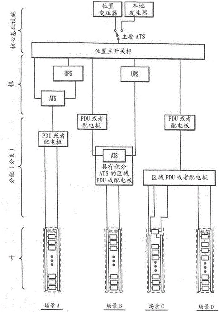
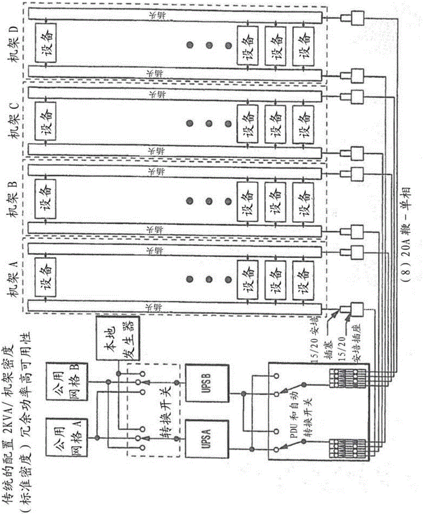
[0074] The following description is structurally divided into two parts. Part 1 discusses the problems involved in data center power distribution and the solutions of the present invention to those problems, and part 2 discusses the construction that can be used to build in a rack / data center architecture The specific method of automatic transfer switch of the characteristics required by the solution of the present invention is described and associated with the rack / data center architecture. It should be noted that the specific method described can also be used for other purposes than constructing an automatic transfer switch.

[0075] I. Background-Power distribution reliability and maintenance issues

[0076] The branch distribution circuit is the area where the most events that cause power loss to the outlet occur. The reason is simple, this is where people tend to make changes in type and load. The most common cause of electrical failure is the tripping of branch circuit brea...


PUM


Abstract

Systems and methods are provided for reliable redundant power distribution. Some embodiments include micro automatic transfer switches (micro-ATSs), including various components and techniques for facilitating reliable auto-switching functionality in a small footprint (e.g., less than ten cubic inches, with at least one dimension being less than a standard NEMA rack height). Other embodiments include systems and techniques for integrating a number of micro-ATSs into a parallel auto-switching module for redundant power delivery to a number of devices. Implementations of the parallel auto-switching module are configured to be mounted in, on top of, or on the side of standard equipment racks. Still other embodiments provide power distribution topologies that exploit functionality of the micro-ATSs and/or the parallel micro-ATS modules.

Description

[0001] cross reference [0002] This application is a non-provisional application of U.S. Patent Application No. 61 / 798,155 entitled "LOAD BALANCING FORPARALLELREDUNDANT POWER DISTRIBUTION" filed on March 15, 2013 and claims priority, and it is also on February 26, 2013 A non-provisional application of US Patent Application No. 61 / 769,688, entitled "PARALLEL REDUNDANT POWERDISTRIBUTION", was filed and claims priority. In addition, this application is a partial continuation application (U.S. Patent Application Publication No. 13 / 208,333 ("'333 application")) filed on August 11, 2011 and entitled "PARALLEL REDUNDANT POWER DISTRIBUTION". US-2012 / 0181869A1), which is a non-provisional application of U.S. Provisional Patent Application No. 61 / 372,752 filed on August 11, 2010 with the title "HIGHLY PARALLEL REDUNDANT POWERDISTRIBUTION METHODS" and comes from August 2010 Co-pending U.S. Provisional Patent Application No. 61 / 372,756, titled "REDUNDANT POWER DISTRIBUTION", filed on the 11...

Claims


Application Information

Patent Timeline
Patent Type & Authority Applications(China)
IPC IPC(8): G06F1/30G06F1/26
CPCG06F1/26H02J9/068
Inventor S.沙佩尔W.帕乔德
Owner ZONIT STRUCTURED SOLUTIONS LLC
Why Eureka
Try Eureka