Artificial hip joint femoral stem

A hip joint and femoral stem technology, applied in the field of human implant prosthesis, can solve the problem that the femoral stem cannot meet the requirements of jumping, running, etc.

Active Publication Date: 2017-05-17
张念非
View PDF10 Cites 8 Cited by
  • Summary
  • Abstract
  • Description
  • Claims
  • Application Information

AI Technical Summary

Problems solved by technology

[0005] The present invention provides a femoral stem of the artificial hip joint, which can withstand greater stress, so as to at least solve the problem that the currently used femoral stem of the artificial hip joint cannot satisfy jumping and running

Method used


Image

  • Artificial hip joint femoral stem
  • Artificial hip joint femoral stem
  • Artificial hip joint femoral stem

Examples


no. 1 example

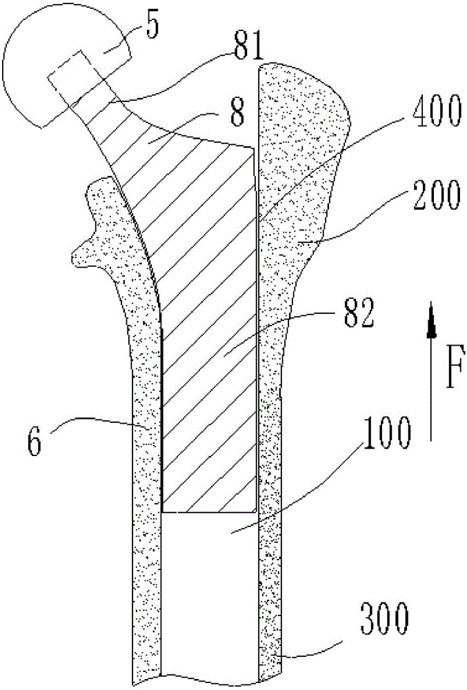
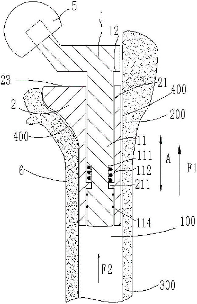
[0030] Such as figure 2 As shown, the femoral stem of the present invention includes a femoral neck 1 and a stem body 2 . The upper end of the femoral neck 1 is usually an oblate structure, the upper end of the femoral neck 1 is connected with the femoral head 5, and is coupled with the acetabular cup (not shown) by the femoral head 5, and the handle 2 is connected with the femoral head 5. It is inserted into the bone marrow cavity 100 of the femur 6 . The part of the handle body 2 and the bone ingrowth of the femur 6 is the proximal end, and the part that is away from the bone ingrowth into the medullary cavity (100) is the distal end. A channel 21 is provided in the handle body 2 , and the channel 21 is a through hole with upper and lower openings, and the channel 21 communicates with the bone marrow cavity 100 through its open lower end. And the femoral neck 1 has a transmission rod 11 extending downward from the upper end, the transmission rod 11 is inserted into the ch...

no. 2 example

[0041] The structure of the second embodiment is basically the same as that of the first embodiment, except that the groove of the transmission rod and the flange of the channel are interchanged. Such as Figure 5 As shown, there is a second annular groove 214 inside the channel 21 of the handle body 2, and a second annular flange 115 is provided on the transmission rod 11, and the second annular flange 115 is embedded in the second annular groove 214 , and a second elastic element, such as a spring 116 , is disposed in the second annular groove 214 . When the femoral neck 1 is under pressure, the transmission rod 11 presses down the spring 116, and its working principle is the same as that of the first embodiment. The description of its working process is omitted here.

no. 3 example

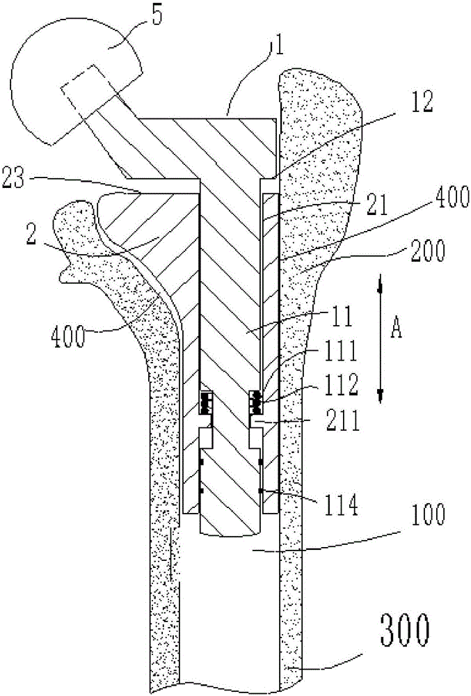
[0043] The structure of the third embodiment is basically the same as that of the first embodiment, as Figure 6 As shown, only the annular groove on the transmission rod 11 and the annular flange on the channel 21 are canceled, and the spring 112 is arranged between the lower surface of the femoral neck 1 and the upper surface of the handle body 2 . By directly compressing the spring 112 through the lower surface of the femoral neck 1, the processing procedure of the femoral stem can be simplified. In addition, a tough block 7 can also be provided between the lower surface 12 of the femoral neck 1 and the upper surface 23 of the handle body 2 to prevent new fibrous granulation tissue from entering the gap between the femoral neck 1 and the handle body 2 .


PUM


Abstract

The invention provides an artificial hip joint femoral stem. The artificial hip joint femoral stem comprises a stem body, a femoral neck and an elastic component. A channel is formed in the stem body. The femoral neck is provided with a drive rod stretching downwards, and the drive rod is inserted into the channel. After the stem body is inserted into a femoral marrow cavity, the channel is communicated with the marrow cavity, pressure, pointing to the far end, borne by the femoral neck is transmitted to a contact interface of the stem body and the femoral near end through the elastic component, meanwhile, the far end of the drive rod protrudes into the marrow cavity to press marrow internal fluid, the pressure, pointing to the far end, borne by the femoral neck is shared jointly by the contact interface and sclerotin at the femoral far end, full femur bears the pressure, and along with disappearing of the pressure borne by the femoral neck, the femoral neck is reset through the elastic component. Mechanical or hydraulic drive is adopted, stress borne by the femoral neck is transmitted to the sclerotin at the femoral near end and the femoral far end, the stress area of a femoral stem prosthesis during stress transmitting is increased, and the requirements of people after hip replacement for jumping, running and other aggravating activities can be met.

Description

technical field [0001] The invention relates to a human body implant prosthesis, in particular to a femoral stem of artificial hip joints. Background technique [0002] A femoral stem is a surgical implant used to replace the femoral portion of the human hip joint. figure 1 A prior art femoral stem 8 is shown in a state inserted into the femoral canal of a femur 6 , comprising a substantially cylindrical femoral neck 81 and a substantially rod-shaped stem body 82 . The handle 82 extends from the femoral neck 81 and is inserted into the medullary cavity of the femur. The femoral neck 81 is connected to the femoral head 5, and the femoral head 5 is embedded in the acetabular prosthesis (not shown). The femoral head 5 can rotate in the acetabular prosthesis. After the handle body 82 is inserted into the femoral cavity, various forms can be used to connect and fix the handle body with the inner wall of the proximal femur, such as bone cement and press-fit biological fixation, ...

Claims


Application Information

Patent Timeline
Patent Type & Authority Applications(China)
IPC IPC(8): A61F2/36
CPCA61F2/3662A61F2/367A61F2/3672A61F2/3676A61F2002/2825A61F2002/30565A61F2002/3625A61F2002/3652A61F2002/3678
Inventor 张念非
Owner 张念非
Why Eureka
Try Eureka