
High rope descent control device

A descending device and rope technology, applied in life-saving equipment, building rescue, etc., can solve the problems of unsatisfactory descending effect, high production cost, inconvenient operation, etc., and achieve light weight, simple structure, and easy operation Effect

Active Publication Date: 2017-05-17
HUBEI CHIBI SALFER FRICTION MATERIAL
View PDF8 Cites 1 Cited by
  • Summary
  • Abstract
  • Description
  • Claims
  • Application Information

AI Technical Summary

Problems solved by technology

However, the current various descending devices have disadvantages such as large volume, complex structure, high production cost, inconvenient operation, and unsatisfactory descending effect.

Method used


Image

  • High rope descent control device
  • High rope descent control device

Examples


Embodiment Construction

[0036] The principles and features of the present invention are described below in conjunction with the accompanying drawings, and the examples given are only used to explain the present invention, and are not intended to limit the scope of the present invention.

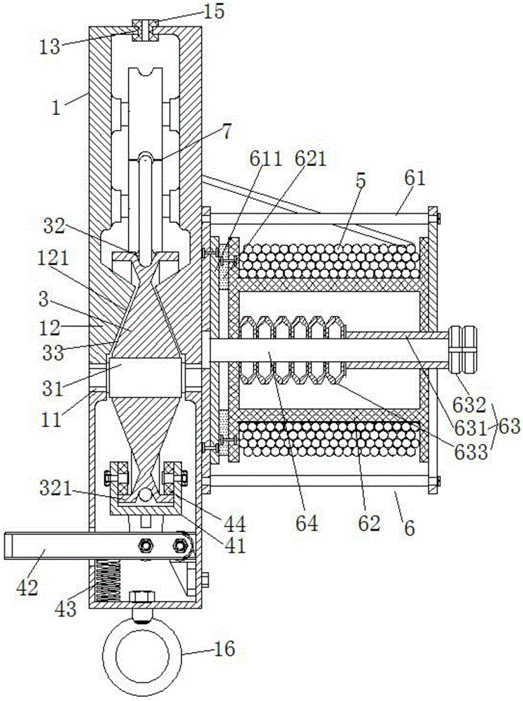
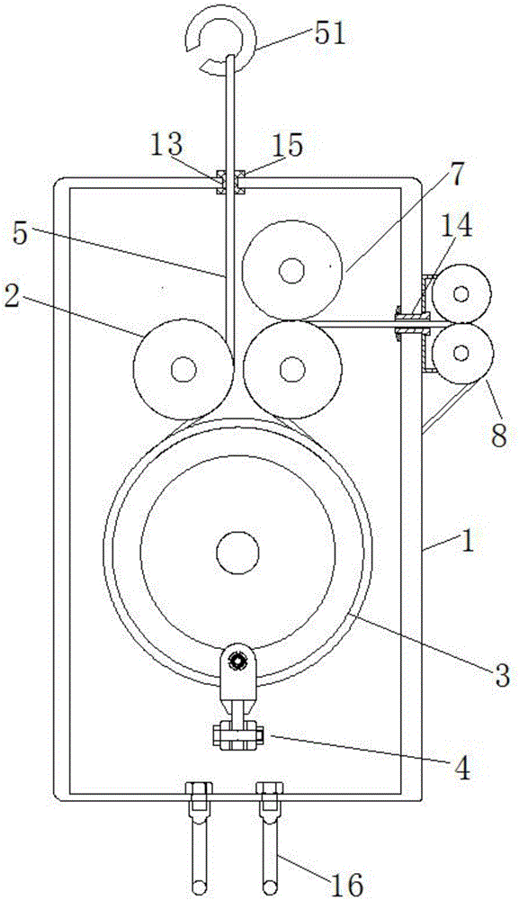
[0037] Example: such as figure 1 and 2 As shown, the high-altitude rope descending device of this embodiment includes a box body 1, a brake wheel 3, an elastic braking mechanism 4, a rope 5 and a rope winding and pay-off device 6 for adjusting the pay-off speed of the above-mentioned rope 5;

[0038] The above-mentioned brake wheel 3 is vertically arranged in the above-mentioned box body 1, and the middle part is axially provided with a wheel shaft 31 passing through it. Rotate on the side wall of the box body 1, and move up and down along the side wall of the box body 1;

[0039] The friction brake parts 12 are symmetrically arranged on the inner walls of both sides of the above-mentioned box body 1. When the abo...


PUM


Abstract

The invention relates to a high rope descent control device, which comprises a box body, a brake wheel, an elastic brake mechanism, a rope, and a rope winding and pay-off device for adjusting the rope pay-off speed. The brake wheel is vertically arranged in the box body; a wheel shaft penetrating through the brake wheel is axially arranged in the middle part of the brake wheel; two ends of the wheel shaft are arranged on two side walls of the box body; the wheel shaft can rotate relative to the side walls of the box body, and can move up and down along the side walls of the box body; friction brake parts are symmetrically arranged on inner walls at two sides of the box body; when the brake wheel moves up and down, two side end faces of the brake wheel can press against or separate from the inner sides of the two friction brake parts; the elastic brake mechanism is arranged in the box body, is located under the brake wheel, and is movably connected with the elastic brake wheel; the rope winding and pay-off device is arranged on the box body; and one end of the rope penetrates through an outlet of the rope and then winds in the rope winding and pay-off device. The high rope descent control device has the advantages of simple structure, convenience in use, good slow descent effect, high safety factor, small volume, light weight, and simplicity in operation.

Description

technical field [0001] The invention relates to high-altitude rescue equipment, in particular to a high-altitude rope descent device. Background technique [0002] When accidents occur in high-altitude operations, or fires, earthquakes and other dangerous situations occur in high-altitude buildings, people need a safe and reliable descending device to escape from a high altitude. However, the present various descending devices have the disadvantages of bulky volume, complex structure, high manufacturing cost, inconvenient operation, and unsatisfactory descending effect. Contents of the invention [0003] The technical problem to be solved by the present invention is to provide a high-altitude rope descent device, which effectively overcomes the defects of the prior art. [0004] The technical solution of the present invention to solve the above-mentioned technical problems is as follows: a high-altitude rope descending device, including a box body, a brake wheel, an elast...

Claims


Application Information

Patent Timeline
IPC IPC(8): A62B1/18
CPCA62B1/18
Inventor 郭东辉伍焕章程时忠
Owner HUBEI CHIBI SALFER FRICTION MATERIAL
Learn More