
Energy-saving waste gas treatment facility

A waste gas treatment and energy-saving technology, applied in gas treatment, use of liquid separation agents, membrane technology, etc., can solve the problems of inconvenient use, insufficient purification, and unreasonable structural design.

Inactive Publication Date: 2017-05-17
NINGXIA QIKAI ENERGY SAVING EQUIP
View PDF6 Cites 0 Cited by
  • Summary
  • Abstract
  • Description
  • Claims
  • Application Information

AI Technical Summary

Problems solved by technology

[0002] The exhaust gas produced in the production of industrial boilers can be basically divided into two categories: separation method and conversion method, mainly using purification equipment. However, the current industrial boiler exhaust gas treatment equipment is unreasonable in structure design, and its purification is not thorough enough. The gas is not up to standard, and it is inconvenient to use

Method used


Image

  • Energy-saving waste gas treatment facility

Examples


Embodiment Construction

[0011] In order to make the object, technical solution and advantages of the present invention clearer, the present invention will be further described in detail below in conjunction with the accompanying drawings and embodiments. It should be understood that the specific embodiments described here are only used to explain the present invention, not to limit the present invention.

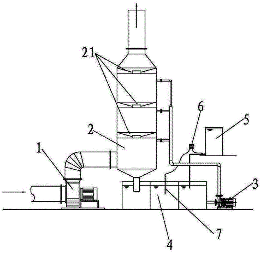
[0012] See figure 1 As shown: the present invention includes a boiler induced draft fan 1, a swirl plate tower 2, a circulating water pump 3, and a circulating water tank 4. One end of the boiler induced draft fan 1 is connected to the swirl plate tower 2, and a circulating water tank 4 is arranged under the swirl plate tower 2 One side of the circulating water tank 4 is provided with a circulating water pump 3, the input end of the circulating water pump 3 is connected to the circulating water tank 4, the output end of the circulating water pump 3 is connected with the tower body of the swirl plat...


PUM


Abstract

The invention relates to the technical field of environment-friendly purifying facilities, particularly an energy-saving waste gas treatment facility which comprises a boiler induced fan, a cyclone plate tower, a circulating water pump and a circulating water tank, wherein one end of the boiler induced fan is connected with the cyclone plate tower; the circulating water tank is arranged below the cyclone plate tower; one side of the circulating water tank is provided with the circulating water pump; the input end of the circulating water pump is connected with the circulating water tank, and the output end of the circulating water pump is connected with the tower body of the cyclone plate tower through a water pipe; two or more cyclone plates are arranged in the cyclone plate tower; and a dosing barrel and a tester are arranged in the circulating water tank. The energy-saving waste gas treatment facility has the advantages of simple and scientific structural design, energy saving and environment friendliness, and can purify waste gas thoroughly.

Description

technical field [0001] The invention relates to the technical field of environmental protection purification equipment, in particular to an energy-saving waste gas treatment equipment. Background technique [0002] The exhaust gas produced in the production of industrial boilers can be basically divided into two categories: separation method and conversion method, mainly using purification equipment. However, the current industrial boiler exhaust gas treatment equipment is unreasonable in structure design, and its purification is not thorough enough. The gas is not up to standard, and it is also inconvenient to use. Contents of the invention [0003] The purpose of the present invention is to provide an environmental protection equipment for waste gas treatment in view of the deficiencies of the prior art, which has simple and scientific structural design, energy saving and environmental protection, and thorough purification of waste gas. [0004] In order to achieve the ...

Claims


Application Information

Patent Timeline
IPC IPC(8): B01D53/78B01D53/96B01D47/00
CPCB01D53/78B01D47/00B01D53/96B01D2258/02B01D2258/0283
Inventor 卡文艳季晓刚
Owner NINGXIA QIKAI ENERGY SAVING EQUIP
Learn More