Clamper

A clamper and clamping claw technology, applied in the high-throughput field, can solve the problems of reducing the operating positioning device of the experimental system, and the inability to integrate the feeding/subtracting system with the clamping system, so as to improve the experimental efficiency and reduce the Ineffective running process, reducing the effect of running positioning device

Active Publication Date: 2017-05-17
王学军
View PDF5 Cites 0 Cited by
  • Summary
  • Abstract
  • Description
  • Claims
  • Application Information

AI Technical Summary

Problems solved by technology

[0005] The embodiment of the present application provides a clamper, which solves the technical problem that the feeding / reducing system and the clamping system cannot be integrated in the prior art, realizes the reduction of the operating positioning device of the experimental system, and reduces the invalidity of the experimental device Run the process to improve the efficiency of the experiment

Method used


Image

  • Clamper
  • Clamper
  • Clamper

Examples


Embodiment 1

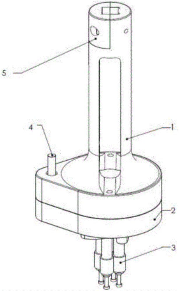
[0030] See below figure 1 , specifically introduces the structure of a clamper.

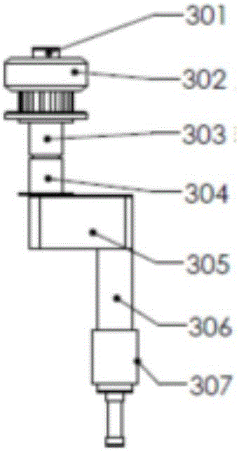
[0031] A clamper comprising an upper base 1 with a first through hole; a lower base 2 with a second through hole; clamping claws 3, the clamping claws 3 is arranged on the lower surface of the lower base 2; the drive shaft assembly 4, the drive shaft assembly 4 is connected with the clamping claw 3, and is used to drive the clamping claw 3 to move so as to clamp the work object; plus The material adding / subtracting channel 9 is located at the center of the holder and above the clamped workpiece, so that it is possible to add or subtract material to the workpiece during clamping.

[0032] Each element of the holder will be described in detail below.

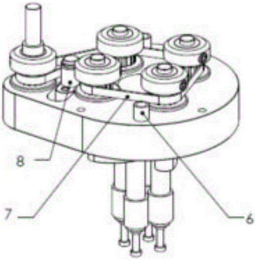
[0033] First, introduce the upper base 1 and the lower base 2, see figure 1 as well as figure 2 . The upper base 1 and the lower base 2, the upper base 1 is provided with a first through hole, the lower base 2 is provided with a second through ...

Embodiment 2

[0038] In order to more clearly introduce the clamper provided by the embodiment of the present application, the embodiment of the present application also provides a method of using the clamper, as follows:

[0039] The use process of the holder is as follows: before use, the holder needs to be connected to the mechanical arm of the matching experimental equipment; through the connection between the pressing block 5 and the upper base 1 and the reserved interface on the mechanical arm, the clamping The holder is fixed on the mechanical arm of the experimental equipment. At the same time, the drive shaft assembly 4 is connected to the corresponding motor on the mechanical arm; The position of the container or object, the controllable motor controls the gripper to start running and grip the target reaction container or object, and then the gripper grips the target reaction container or object and moves to the target position with the mechanical arm; in the process The feeding / s...


PUM


Abstract

The invention discloses a clamper and relates to the field of the high throughput technology. The clamper solves the technical problem that the existing clamper cannot integrate a charging/discharging system and a clamping system. The clamper comprises an upper base which is provided with a first through hole, a lower base which is provided with a second through hole, a clamping jaw which is arranged on the lower surface of the lower base, a driving shaft which is connected to the clamping jaw and is used for driving the clamping jaw to clamp a work piece, and a burdening assembly which is used for burdening of the work piece through the first and second through holes. The charging/discharging system and the clamping system are integrated so that a running and positioning device of the experimental system is avoided, an ineffective running process of the experimental device is avoided and experimental effects are improved.

Description

technical field [0001] The invention relates to a high-throughput technical field, in particular to a holder. Background technique [0002] With the development of science and technology, the experimental facilities in various fields are also constantly improving, and the need to frequently add / reduce materials to the reaction vessel and transfer the position of the reaction vessel during the test process has always been a difficulty in improving the efficiency of the experiment. At present, in the laboratory, the feeding / removing of the sample and the transfer process of the reaction vessel are carried out independently and step by step, that is, firstly, the clamping transfer system transfers the reaction vessel to the target position, and then the clamping transfer system returns to the initial position, and the feeding / removing The material reduction system runs to the target position of the reaction vessel, and then performs the feeding / reducing operation, and finally t...

Claims


Application Information

Patent Timeline
Patent Type & Authority Applications(China)
IPC IPC(8): B01J4/00B01J19/00
CPCB01J4/007B01J19/0053
Inventor 王学军
Owner 王学军
Why Eureka
Try Eureka