Sand mould used for casting machine tool double-arm vertical column casting and manufacturing method of sand mould

A dual-arm, casting technology, applied in the direction of casting molding equipment, casting molds, casting mold components, etc., can solve the problems of difficult control of quality and dimensional accuracy, increased cleaning difficulty, and difficult control of size, so as to avoid the gap between core molds Insufficient tightness, avoiding loose positioning, and improving production efficiency

Active Publication Date: 2017-05-17
NINGXIA KOCEL MOLD
View PDF3 Cites 13 Cited by
  • Summary
  • Abstract
  • Description
  • Claims
  • Application Information

AI Technical Summary

Problems solved by technology

[0003] The structure of the double-arm column is as follows: figure 1 As shown, there are mostly inner cavities along the periphery, the main body wall thickness is thin, and the structure is complex
The traditional casting process is difficult, and the quality and dimensional accuracy are difficult to control
Mainly reflected in: 1, left side arm 10, right side arm 20 inner cavities and two arms crotch 30 three parts are relatively independent in structure (as figure 2 As shown), in the traditional casting process, these three parts should be designed as three sand cores independent of each other. When the core mold is assembled, it needs to be cored separately. The sand core is easy to loose during the pouring process, resulting in choking defects and wall thickness of the casting. Uneven defects; 2. The gap between the sand cores is not tight enough when setting the core, and the molten iron is randomly strung together during the mold filling, resulting in increased casting seams and increased difficulty in cleaning; 3. When assembling the core mold, it is necessary to make a special clamping plate for size measurement to Accurate control of wall thickness is achieved, the operation is difficult and the size is not easy to control

Method used


Image

  • Sand mould used for casting machine tool double-arm vertical column casting and manufacturing method of sand mould
  • Sand mould used for casting machine tool double-arm vertical column casting and manufacturing method of sand mould
  • Sand mould used for casting machine tool double-arm vertical column casting and manufacturing method of sand mould

Examples


Embodiment Construction

[0028] Embodiments of the present invention will be described in detail below in conjunction with the accompanying drawings.

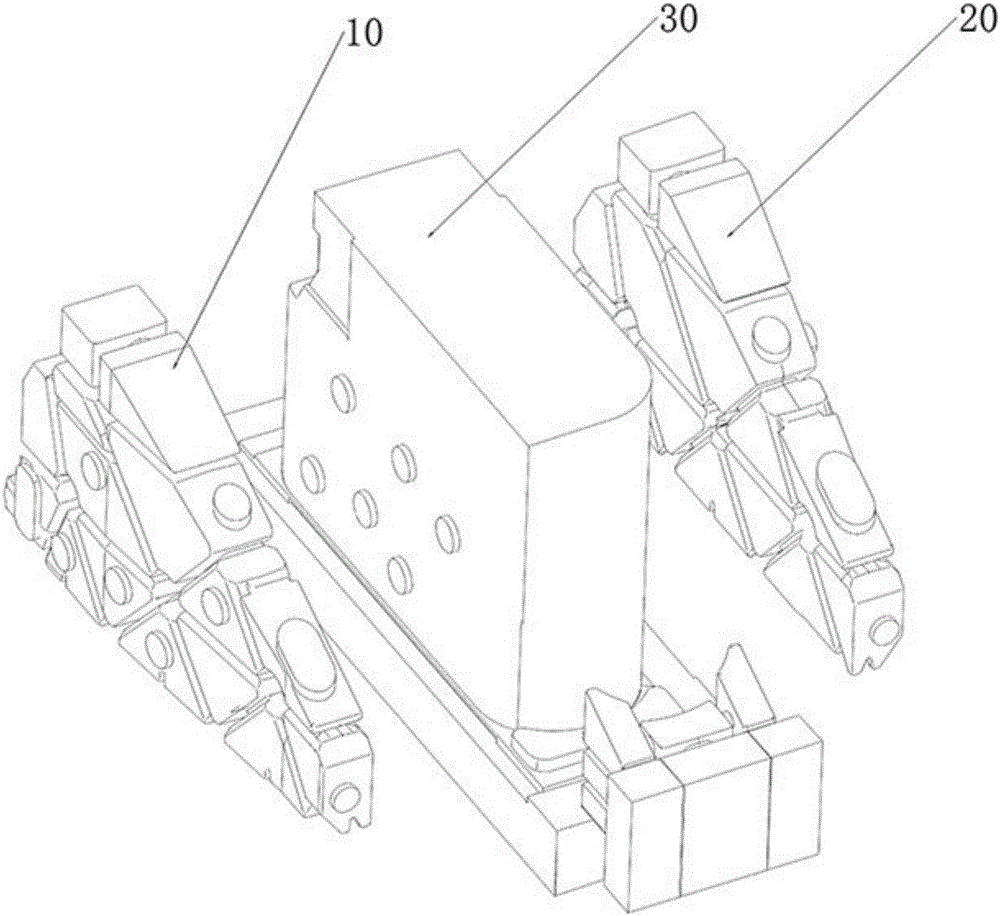
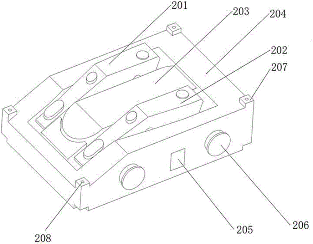
[0029] like image 3 As shown, one embodiment of the present invention provides a sand mold for casting double-arm column castings of machine tools, including a first mold unit 100 for forming the outer contour shape of the bottom of the double-arm column castings of machine tools, for forming double-arm column castings of machine tools. The second casting unit 200 of the inner cavity structure of the arm column casting, the outer profile of the side wall, and the outer profile of the facade is used to form the third casting unit 300 of the outer profile shape of the side wall, slope, and top surface of the double arm column casting of the machine tool.

[0030] like image 3 As shown, the second casting unit 200 is integrally formed by 3D printing and forming technology, and its structure includes a left arm forming part 201 for forming the inner cav...


PUM


Abstract

The invention provides a sand mould used for casting a machine tool double-arm vertical column casting. The sand mould comprises a first casting mould unit, a second casting mould unit and a third casting mould unit, wherein the first casting mould unit is used for forming the bottom outer outline shape of the machine tool double-arm vertical column casting; the second casting mould unit is used for forming an inner cavity structure, a side wall outer outline and a vertical face outer outline of the machine tool double-arm vertical column casting; the third casting mould unit is used for forming side wall, inclined face and top face outer outline shapes of the machine tool double-arm vertical column casting; the second casting mould unit comprises a left arm moulding part used for moulding a left arm inner cavity structure of the machine tool double-arm vertical column casting, a right arm moulding part used for moulding a right arm inner cavity structure of the machine tool double-arm vertical column casting, a double-arm in-leg moulding part used for moulding a double-arm in-leg inner cavity structure of the machine tool double-arm vertical column casting, and an outer moulding part used for moulding an outer outline structure of the machine tool double-arm vertical column casting. Besides, the invention provides a manufacturing method of the sand mould and an assembling method of the sand mould.

Description

technical field [0001] The invention relates to the technical field of casting, and more specifically, to a sand mold for casting machine tool double-arm column castings and a manufacturing method thereof. Background technique [0002] Double-arm column castings are used in horizontal machining centers. As the main structural components for the lathe bed and machining tools, they require good mechanical properties and high requirements for dimensional accuracy and internal defects. [0003] The structure of the double-arm column is as follows: figure 1 As shown, there are mostly inner cavities along the periphery, the main body wall thickness is thin, and the structure is complex. The traditional casting process is difficult, and the quality and dimensional accuracy are difficult to control. Mainly reflected in: 1, left side arm 10, right side arm 20 inner cavities and two arms crotch 30 three parts are relatively independent in structure (as figure 2 As shown), in the t...

Claims


Application Information

Patent Timeline
Patent Type & Authority Applications(China)
IPC IPC(8): B22C9/02B22C9/22B22C9/10B33Y10/00
CPCB22C9/02B22C9/10B22C9/108B22C9/22B33Y10/00
Inventor 苗润青
Owner NINGXIA KOCEL MOLD
Why Eureka
Try Eureka