Reverse osmosis filtering water purifying tank for detecting quality of water

A technology of filtering water tank and reverse osmosis, which is applied in osmosis/dialysis water/sewage treatment, water/sewage treatment, water/sludge/sewage treatment, etc. , inconvenient use, etc.

Inactive Publication Date: 2017-05-17
重庆昌林消防工程有限公司
View PDF0 Cites 2 Cited by
  • Summary
  • Abstract
  • Description
  • Claims
  • Application Information

AI Technical Summary

Problems solved by technology

[0002] At present, due to the provision of a fire-fighting water layer according to regulations, the current storage tank forms a "dead water layer" that is often in a static state. And the breeding base of microorganisms. In addition, the surface of the existing pool wall is rough, with many holes and trachoma. Dust, various insect eggs, and spores of bryophytes are very easy to adhere to or hide in it; moreover, the general pool There is no edge protection around the inspection hole at the top. Even if the hole cover is covered, rainwater can often seep into the pool through the gap, causing pollution. Moreover, the hole cover is usually prefabricated with concrete, which is very heavy and inconvenient to use. It is also easy to cover after use. If it is not strict, it provides conditions for small animals such as dust, microorganisms, various insects, bryophyte spores and even mice to enter the storage tank to pollute the pool water; With the prolongation of time, it will continue to decrease until it reaches the storage tank on the roof. After testing, the residual chlorine content for disinfection is close to zero.

Method used


Image

  • Reverse osmosis filtering water purifying tank for detecting quality of water

Examples


Embodiment Construction

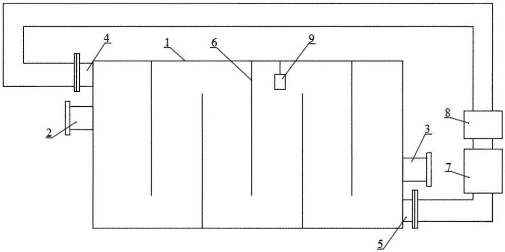
[0013] The present invention will be further described below in conjunction with accompanying drawing:

[0014] Such as figure 1 As shown, a reverse osmosis filtration clean water tank for detecting water quality includes a water storage tank, including a water storage tank 1, and the water storage tank 1 is provided with a water inlet A2, a water outlet A3, and an inlet connected to the water storage tank 1. The water outlet B4 and the water outlet B5, the interior of the water storage tank 1 are provided with a plurality of baffles 6 arranged in the vertical direction, each baffle 6 and the side wall of the water storage tank 1 have a water drop hole, adjacent The drain holes of the baffle plate 6 are respectively arranged on the upper and lower sides of the water storage tank 1, the water inlet A2 and the water inlet B4 are respectively arranged on the upper part of the left side of the water storage tank 1, and the discharge port A3 and the discharge port B5 are all locate...


PUM


Abstract

The invention discloses a reverse osmosis filtering water purifying tank for detecting the quality of water. The reverse osmosis filtering water purifying tank comprises a water storage tank, the water storage tank is provided with a water inlet A, a water outlet A, a water inlet B and a water outlet B which communicate with the water storage tank, a plurality of vertically arranged baffle plates are arranged in the water storage tank, a water falling hole is arranged between every baffle plate and the sidewall of the water storage tank, the water falling holes of the adjacent baffle plates are arranged at the upper side and the lower side of the water storage tank, the water inlet A and the water inlet B are respectively arranged at the upper portion of the left side of the water storage tank, the water outlet A and the water outlet B are positioned at the lower portion of the right side of the water storage tank, the water outlet B is sequentially connected with a circulating water pump and a water purifying filtering device through a pipeline, and the water outlet of the water purifying filtering device is connected with the water inlet B of the water storage tank through a pipeline. the reverse osmosis filtering water purifying tank prevents regular stopping of the use of the water storage tank and artificial cleaning of the water storage tank, can be continuously used for a long term, and allows the quality of water in the water storage tank to keep health standards before the entrance of the water to the water storage tank.

Description

technical field [0001] The invention relates to a reverse osmosis filter clean water tank for detecting water quality. Background technique [0002] At present, due to the provision of a fire-fighting water layer according to regulations, the current storage tank forms a "dead water layer" that is often in a static state. And the breeding base of microorganisms. In addition, the surface of the existing pool wall is rough, with many holes and trachoma. Dust, various insect eggs, and spores of bryophytes are very easy to adhere to or hide in it; moreover, the general pool There is no edge protection around the inspection hole at the top. Even if the hole cover is covered, rainwater can often seep into the pool through the gap, causing pollution. Moreover, the hole cover is usually prefabricated with concrete, which is very heavy and inconvenient to use. It is also easy to cover after use. If it is not strict, it provides conditions for small animals such as dust, microorganis...

Claims


Application Information

Patent Timeline
Patent Type & Authority Applications(China)
IPC IPC(8): C02F1/44
CPCC02F1/441C02F2209/001C02F2301/028C02F2303/20C02F2303/22
Inventor 李昌林
Owner 重庆昌林消防工程有限公司
Why Eureka
Try Eureka