Air-flow ultrasonic sound source device for molten iron pretreatment

A molten iron pretreatment, air flow technology, applied in the direction of fluid using vibration, etc., can solve problems such as the difficulty of applying ultrasonic waves, the inability to withstand the huge stress of high-power ultrasonic waves, and the impact of ultrasonic input, etc., to achieve simple structure, improved service life, and improved utilization rate effect

Active Publication Date: 2018-08-28
WUHAN UNIV OF SCI & TECH
View PDF5 Cites 0 Cited by
  • Summary
  • Abstract
  • Description
  • Claims
  • Application Information

AI Technical Summary

Problems solved by technology

However, when using the traditional horn-type ultrasonic device, the horn will not be able to withstand the huge stress brought by high-power ultrasonic waves in the high-temperature molten iron. At the same time, if there is any small defect in the horn, it will greatly affect the input of ultrasonic waves. Therefore, it has caused great difficulties in the application of ultrasonic waves in molten iron.

Method used


Image

  • Air-flow ultrasonic sound source device for molten iron pretreatment
  • Air-flow ultrasonic sound source device for molten iron pretreatment
  • Air-flow ultrasonic sound source device for molten iron pretreatment

Examples


Embodiment 1

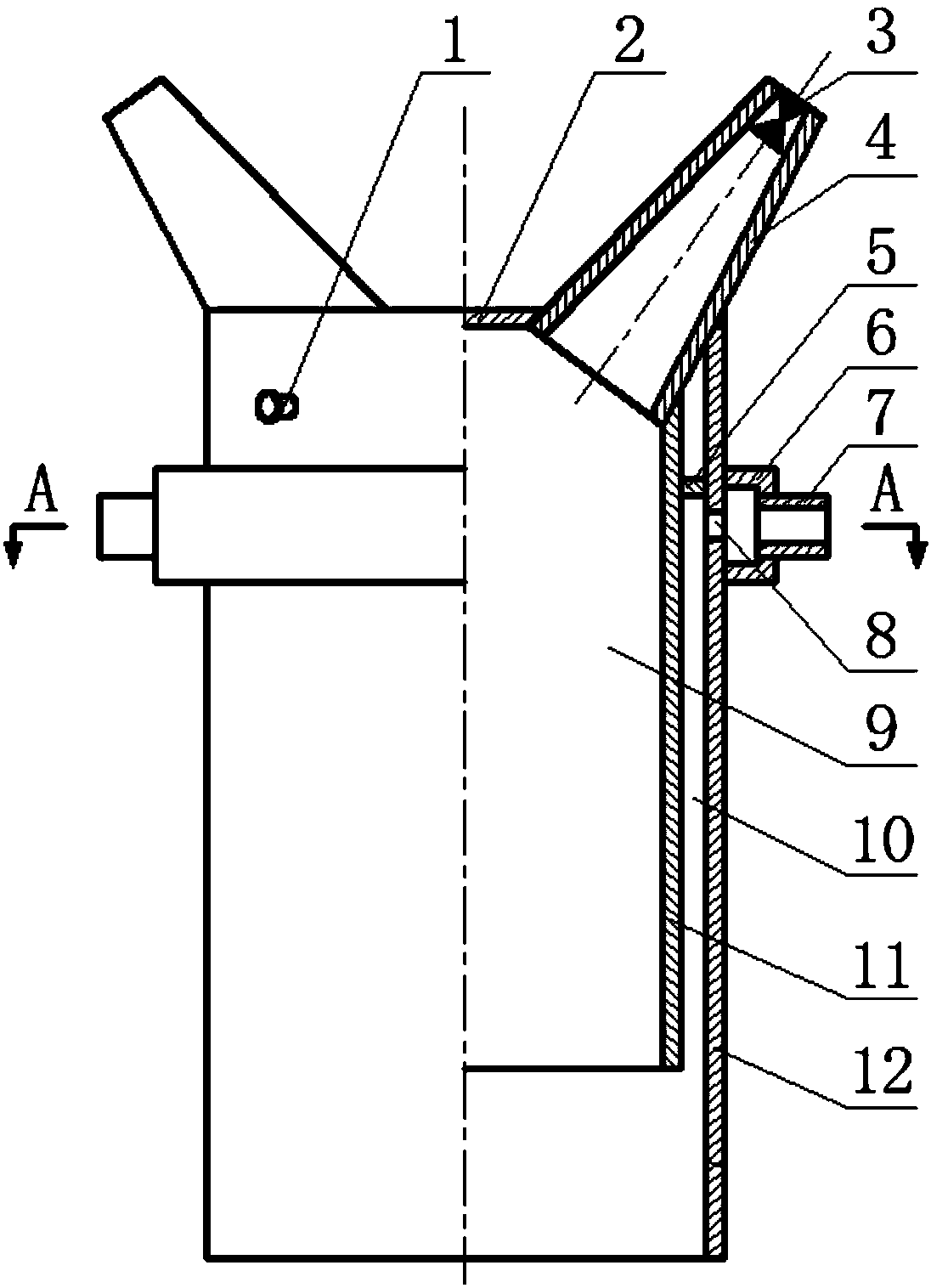
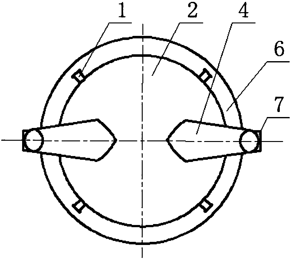
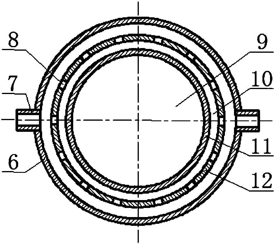
[0025] Embodiment 1, with reference to figure 1 , 2 3. The upper ends of the inner casing 11 and the outer casing 12 of the present invention are fixed with a circular top plate 2 , and a gas resonance cavity 9 is formed between the circular top plate 2 and the inner casing 11 . The tapered waveguide 4 is inclined symmetrically and fixed on the circular top plate 2 , the inner sleeve 11 and the outer sleeve 12 .

[0026] The tapered waveguide 4 communicates with the gas resonance cavity 9, and a Hartmann whistle 3 is installed on the top of the tapered waveguide. With the present invention, the high-pressure gas passes through the Hartmann whistle to generate ultrasonic waves. Since there is no lack of high-pressure gas source in the iron and steel plant, the problem of the high-pressure gas source is well solved and the use cost is reduced; meanwhile, the Hartmann whistle has a simple structure and low cost. , Easy to install, high ultrasonic power generated. The Hartmann ...

Embodiment 2

[0033] Embodiment 2, structure and method of use are the same as embodiment 1, and the difference is that the technical parameters of each part are as follows:

[0034] The inclined angle of the symmetrically inclined tapered waveguide 4 is 55-70°. The inner diameter of the bottom end of the tapered waveguide is 0.4 to 0.45 times the inner diameter of the inner sleeve, the inner diameter of the top is 0.25 to 0.3 times the inner diameter of the inner sleeve, and the height of the tapered waveguide is 1.75 to 2 times the inner diameter of the inner sleeve .

[0035]The inner diameter of the inner casing 11 is 0.2 to 0.25 times the diameter of the opening of the molten iron ladle 13 to be pretreated. The height of the outer casing 12 is 1.375 to 1.5 times the height of the ladle to be pretreated, and the distance between the lower end of the outer casing and the lower end of the inner casing is 0.225 to 0.25 times the height of the outer casing. The diameter of the air guide h...


PUM

PropertyMeasurementUnit
diameteraaaaaaaaaa
thicknessaaaaaaaaaa

Abstract

The invention relates to an airflow-type ultrasonic wave sound source device used for molten iron pretreatment. A round top plate is arranged on an inner sleeve and an outer sleeve. A gas resonant cavity is formed between the round top plate and the inner sleeve. Obliquely-arranged conical waveguide tubes communicate with the gas resonant cavity. Hartmann whistles are arranged at the top ends of the conical waveguide tubes. An annular gas gathering cover is arranged outside the outer sleeve. The outer sleeve is provided with gas guide holes, and the gas guide holes communicate with the annular gas gathering cover. An annular gas baffle is arranged between the inner sleeve and the outer sleeve. The inner sleeve, the outer sleeve and the annular gas baffle are surrounded to form a gas exhaust channel. The annular gas gathering cover is connected with gas collecting system connectors. In the using process, the airflow-type ultrasonic wave sound source device is suspended above a ladle and cannot make contact with molten iron. High pressure gas generates high power ultrasonic waves through the Hartmann whistles and then forms resonance with a gas pillar in the gas resonant cavity, and the high power ultrasonic waves are input to the molten iron. Gas is recycled. The high pressure gas is recycled through the gas exhaust channel, the gas guide holes and the like. The airflow-type ultrasonic wave sound source device is simple in structure, easy to manufacture, convenient to operate and capable of well leading the ultrasonic waves into the molten iron.

Description

technical field [0001] The invention belongs to the application field of power ultrasonic technology. In particular, it relates to an airflow type ultrasonic sound source device for molten iron pretreatment. Background technique [0002] The method of hot metal pretreatment and desulfurization can not only reduce the desulfurization burden of the blast furnace and increase the productivity of the blast furnace, but also reduce the desulfurization burden of the converter steelmaking and even remove the desulfurization link. The injection method is a widely used molten iron desulfurization technology. During the desulfurization process of the injection method, the magnesium particles and the auxiliary desulfurization agent calcium oxide particles that are not ready to react in the future are either wrapped in the bubbles or entrained in the bubble flow area and rise accordingly. . However, due to the high vapor pressure of magnesium at high temperature, the volume of the gen...

Claims


Application Information

Patent Timeline
Patent Type & Authority Patents(China)
IPC IPC(8): C21C1/02C21C7/064B06B1/20
CPCB06B1/20C21C1/02C21C7/064
Inventor 金焱祝俊俊常正昇薛正良
Owner WUHAN UNIV OF SCI & TECH
Why Eureka
Try Eureka