Hydraulic shock absorber

A technology of hydraulic shock absorbers and limit baffles, which is applied in shock absorbers, springs/shock absorbers, shock absorbers, etc., and can solve problems such as complex structures, poor corrosion resistance, and oil leakage

Inactive Publication Date: 2017-05-17
杨文元
View PDF0 Cites 0 Cited by
  • Summary
  • Abstract
  • Description
  • Claims
  • Application Information

AI Technical Summary

Problems solved by technology

The existing hydraulic shock absorbers have poor corrosion resistance, complex structure, poor sealing, and many problems such as oil leakage may occur

Method used


Image

  • Hydraulic shock absorber

Examples


Embodiment Construction

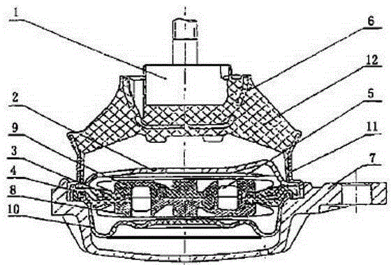
[0011] The present invention will be further explained below in conjunction with the accompanying drawings and embodiments.

[0012] Such as figure 1 As shown, a hydraulic shock absorber is characterized in that it includes a threaded connecting rod 1, a limit baffle 2, a disc-shaped reinforcement ring 4, an inertia channel 5, a metal skeleton 6, a connecting base 7, a rubber main spring seat 11 and The main spring 12; the threaded connecting rod 1 is fixed on the metal skeleton 6, and the main spring 12 is installed on both sides of the metal skeleton 6, and the main spring 12 is connected with the disc-shaped reinforcing ring 4 through the rubber main spring seat 11; the metal A limit baffle 2 is provided under the frame 6, and a disc-shaped reinforcing ring 4 is provided on both sides of the limit baffle 2, and the disc-shaped reinforcing ring 4 is fixedly clamped on the connection base 7; the limit baffle 2 is provided with an inertial Channel 5; the upper inertia channel...


PUM


Abstract

The invention discloses a hydraulic shock absorber. The hydraulic shock absorber is characterized in that the shock absorber comprises a threaded connection rod (1), a limiting baffle (2), disk-shaped reinforcing rings (4), an inertia channel (5), a metal framework (6), a connecting base (7), main spring rubber bases (11) and main springs (12); the threaded connection rod (1) is fixedly arranged on the metal framework (6); the main springs (12) are arranged at the two sides of the metal framework (6) and are connected with the disk-shaped reinforcing rings (4) through the main spring rubber bases (11); the limiting baffle (2) is arranged below the metal framework (6); the disk-shaped reinforcing rings (4) are arranged at the two sides of the limiting baffle (2) and are fixedly clamped onto the connecting base (7); and the inertia channel (5) is arranged inside the limiting baffle (2).

Description

technical field [0001] The invention discloses a shock absorber, in particular to a hydraulic shock absorber. Background technique [0002] Hydraulic shock absorbers are widely used in automobile suspension systems. The principle is that when the frame and the axle move back and forth relative to each other and the piston moves back and forth in the cylinder barrel of the shock absorber, the oil in the shock absorber housing will repeatedly pass through some narrow pores from the inner cavity. into another cavity. At this time, the friction between the liquid and the inner wall and the internal friction of the liquid molecules constitute the damping force for vibration. The hydraulic shock absorber is a new type of shock absorber that has grown up since the 1960s. Its structural feature is that a floating piston is installed at the lower part of the cylinder, and a closed air chamber formed by the floating piston and one end of the cylinder is filled with high-pressure ni...

Claims


Application Information

Patent Timeline
IPC IPC(8): F16F13/06
Inventor 杨文元
Owner 杨文元
Why Eureka
Try Eureka