Valve interior observing device provided with self-luminous industrial endoscope

An observation device and endoscope technology, applied in valve devices, engine components, mechanical equipment, etc., can solve the problems of undiscovered patent publications, inability to directly observe in real time, and reduced work efficiency, so as to extend service life and ensure use. effect, improve work efficiency

Inactive Publication Date: 2017-05-17
天津澳特斯阀门制造有限公司
View PDF0 Cites 3 Cited by
  • Summary
  • Abstract
  • Description
  • Claims
  • Application Information

AI Technical Summary

Problems solved by technology

[0002] At present, valves have been widely used. However, because the valve is a sealed device for conveying pressure fluid medium, the current valve does not have a visual channel to observe the internal situation of the valve. Therefore, the internal situation of the existing valve includes the working process of the opening and closing parts. It is impossible to observe directly in real time. If you need to observe the internal situation of the valve, you need to disassemble the valve from the pipeline, or enter the pipeline and the inside of the valve through the maintenance manhole set on the pipeline to observe when the medium in the pipeline is drained. This observation method not only delays work and time, but also wastes medium and reduces work efficiency. It can be seen that the existing valves can no longer meet the needs of timely grasping the internal situation of the valve and making the medium delivery pipeline run continuously, safely and stably.
[0003] Through searching, no patent publications related to this patent application have been found

Method used


Image

  • Valve interior observing device provided with self-luminous industrial endoscope
  • Valve interior observing device provided with self-luminous industrial endoscope
  • Valve interior observing device provided with self-luminous industrial endoscope

Examples


Embodiment Construction

[0015] In order to further understand the content, features and effects of the present invention, the following embodiments are exemplified and described in detail as follows in conjunction with the accompanying drawings. It should be noted that this embodiment is descriptive, not restrictive, and cannot thereby limit the protection scope of the present invention.

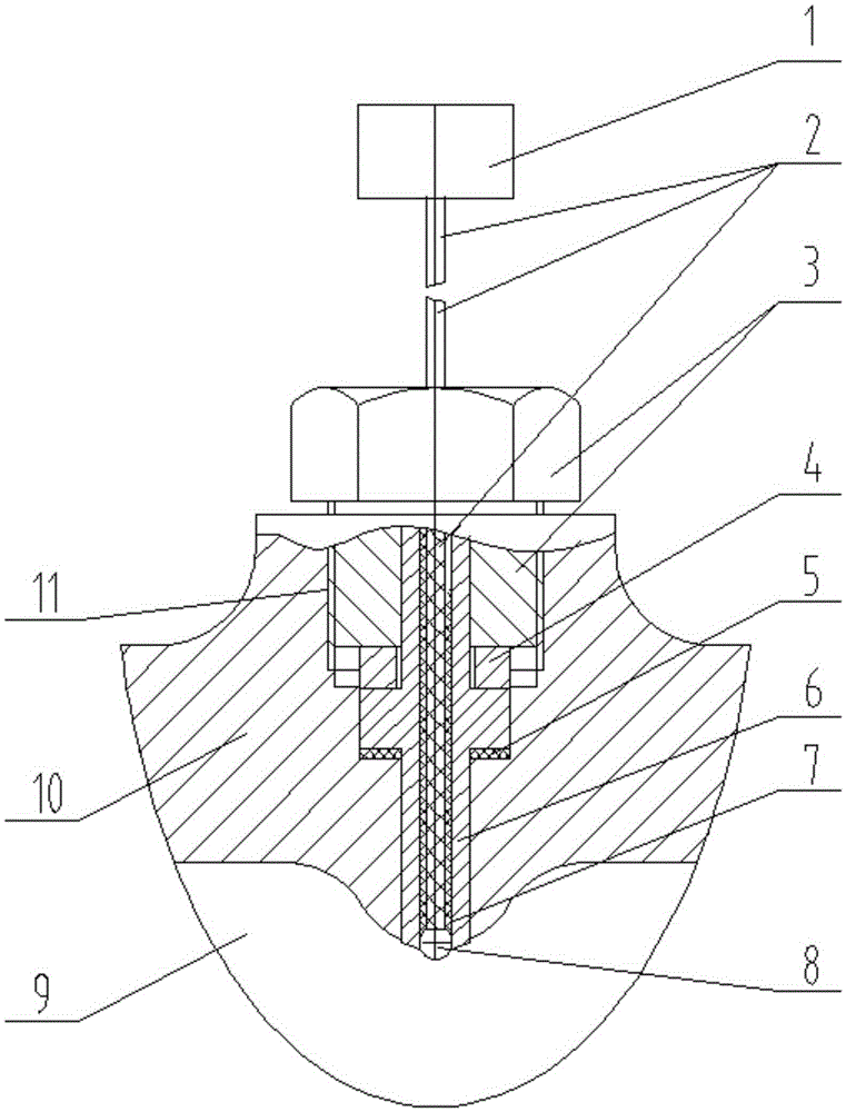
[0016] A valve interior observation device with a self-illuminating industrial endoscope, such as figure 1 As shown, the device includes a through hole 11 made in the valve body 10, an industrial endoscope tip 8 with a self-illuminating function, a conductive light guide 2, a resin sleeve 7, a catheter 6 and a working eyepiece arranged outside the valve Part 1, one end of the through hole is arranged in communication with the cavity 9 of the valve body, and the other end of the through hole extends to the outer surface of the valve body. The through hole can withstand the working pressure difference inside and outs...


PUM


Abstract

The invention relates to a valve interior observing device provided with a self-luminous industrial endoscope. The valve interior observing device comprises a through duct, an industrial endoscope pilot end part with a self-luminous function, a conductive light guiding beam, a resin sleeve, a guide pipe and a working eye lens part, wherein the through duct, the industrial endoscope pilot end part with the self-luminous function, the conductive light guiding beam, the resin sleeve and the guide pipe are arranged in a valve body, and the working eye lens part is arranged outside the valve body. One end of the through duct communicates with an inner cavity of the valve body, and the other end of the through duct extends onto the outer surface of the valve body. The industrial endoscope pilot end part is tightly arranged at one end of the through duct, the other end of the industrial endoscope pilot end part is connected with one end of the conductive light guiding beam, and the other end of the conductive light guiding beam stretches out of the through duct to be connected with the working eye lens part. The valve interior observing device is applied to a valve, the interior condition of the valve can be observed and known at any time or at regular times through the endoscope, time and labor are saved, media are also saved, the working procedure is simplified, and the working efficiency is improved; and by adoption of the device, the requirements for learning about the interior condition of the valve in time and enabling a medium delivery pipeline to operate continuously, safely and stably can be met.

Description

technical field [0001] The invention belongs to the technical field of valve equipment, in particular to a valve interior observation device with a self-illuminating industrial endoscope. Background technique [0002] At present, the valve has been widely used. However, because the valve is a sealed and closed device for conveying pressure fluid medium, the current valve does not have a visual channel to observe the internal situation of the valve, so the internal situation of the existing valve includes the working process of the opening and closing parts. It is impossible to observe directly in real time. If you need to observe and understand the internal conditions of the valve, you need to disassemble the valve from the pipeline, or enter the pipeline and the valve through the maintenance manhole set on the pipeline under the condition of emptying the medium in the pipeline. This observation method not only misses work and time, but also wastes the medium and reduces the...

Claims


Application Information

Patent Timeline
Patent Type & Authority Applications(China)
IPC IPC(8): F16K37/00
CPCF16K37/0058
Inventor 张二南裴叶青段淑清张国栋庞慧高国伟兴冯之春李成敬新蕊
Owner 天津澳特斯阀门制造有限公司
Why Eureka
Try Eureka