
A cooling system for waste-to-energy plant equipment

A technology for cooling systems and power plants, used in lighting and heating equipment, refrigerators, refrigeration and liquefaction, etc., can solve the problems of complicated pipelines, non-recyclable, poor air cooling effect, etc., to achieve high economy, cooling good effect

Active Publication Date: 2017-02-22
如东天楹环保能源有限公司
View PDF4 Cites 0 Cited by
  • Summary
  • Abstract
  • Description
  • Claims
  • Application Information

AI Technical Summary

Problems solved by technology

[0002] Waste-to-energy is the most effective treatment method to achieve "reduction, volume reduction, and recycling" of waste. The continuous and stable operation of waste-to-energy plant equipment ensures timely and harmless treatment of waste. The cooling effect of waste-to-energy equipment has a great impact on equipment The smooth operation is very important, long-term over-temperature operation is easy to damage the equipment
[0003] At present, there are three methods for the equipment cooling system of waste-to-energy plants: 1. Air cooling, which is not effective and requires a separate fan, and the pipeline is relatively complicated; 2. Fresh water cooling, which is prone to freezing of pipelines at low temperatures, resulting in Road equipment is damaged and cannot be recycled, which is wasteful in water-shortage areas; 3. Coolant, the price of coolant is expensive

Method used


Image

  • A cooling system for waste-to-energy plant equipment

Examples


Embodiment Construction

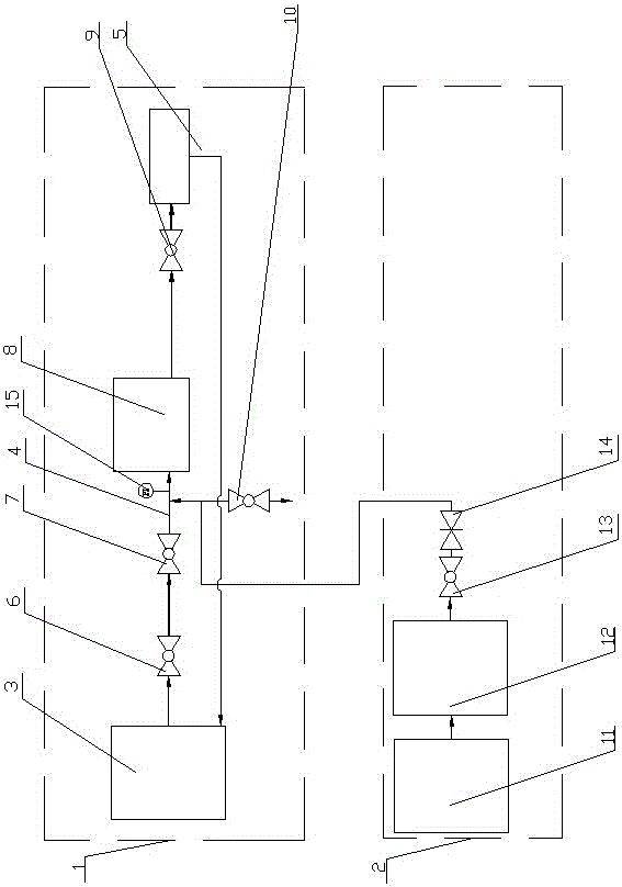
[0015] Such as figure 1 As shown, the present invention includes a circulating water cooling system 1 and a compressed air purging cooling system 2 .

[0016] The circulating water cooling system 1 includes a cooling water pool 3, an atomizing water pipe 4 for atomizing and cooling the equipment 8, and a circulating cooling water recovery pipe 5; the water outlet of the cooling water pool 3 is connected to a first ball valve 6, and the atomizing water pipe 4 is connected to There is a pressure gauge 15, the input end of the atomizing water pipe 4 is connected with the second ball valve 7, the output end of the first ball valve 6 is connected with the input end of the second ball valve 7, and the output end of the second ball valve 7 is also connected with a drain valve 10 ; The input end of the circulating cooling water recovery pipe 5 is used to recover the cooling atomized water, the output end of the circulating cooling water recovery pipe 5 is connected to the cooling wate...


PUM


Abstract

The invention discloses a cooling system of garbage power plant equipment and relates to the technical field of environmental-friendly waste heat power generation. The cooling system comprises a circulating water cooling system body and a compressed air purge cooling system body. The circulating water cooling system body comprises a cooling water pond, an atomizing water pipe used for conducting atomizing cooling on the equipment and a circulating cooling water recovery pipe. The compressed air purge cooling system body comprises an air compression machine room, a compressed air storage tank and a fourth ball valve. The cooling system is good in antifreezing effect, high in cooling efficiency, economical, low in fault rate and suitable for equipment in other fields.

Description

technical field [0001] The invention relates to the technical field of environmental protection waste heat power generation, in particular to an equipment cooling system of a garbage power plant. Background technique [0002] Waste-to-energy is the most effective treatment method to achieve "reduction, volume reduction, and recycling" of waste. The continuous and stable operation of waste-to-energy plant equipment ensures timely and harmless treatment of waste. The cooling effect of waste-to-energy equipment has a great impact on equipment The smooth operation of the machine is very important, long-term over-temperature operation is easy to damage the equipment. [0003] At present, there are three methods for the equipment cooling system of waste-to-energy plants: 1. Air cooling, which is not effective and requires a separate fan, and the pipeline is relatively complicated; 2. Fresh water cooling, which is prone to freezing of pipelines at low temperatures, resulting in Th...

Claims


Application Information

Patent Timeline
Patent Type & Authority Patents(China)
IPC IPC(8): F25D1/02F25B1/00
CPCF25D1/00
Inventor 赵正萍王占磊陈竹李军何志刚
Owner 如东天楹环保能源有限公司
Learn More