Illumination device

A lighting device and lampshade technology, which is applied in the direction of lighting devices, independent lighting devices, lighting device components, etc., can solve the problems of weak energy saving effect, complicated circuit principle, and inapplicability, and achieve convenient use and operation, simple circuit principle, Safe and reliable performance

Inactive Publication Date: 2017-05-17
尤世元
View PDF0 Cites 0 Cited by
  • Summary
  • Abstract
  • Description
  • Claims
  • Application Information

AI Technical Summary

Problems solved by technology

[0004] There are mainly three types of existing energy-saving lamps with automatic dimming: one is the manual shifting type, which uses buttons to adjust the light intensity through manual control. The existing natural light intensity is effectively used, and the adjustment is not automatic; the second is the touch type, which sends a trigger pulse signal to the touch sensing end through the sensing electrode sheet, and adjusts and controls the light intensity and brightness through manual touch. The light mode is affected by the temperature of the touching hand to a certain extent, and cannot accurately and well meet the needs of dimming. It is often not used in some occasions that have strict requirements on light intensity and brightness, such as hospitals, etc.
The third is the infrared induction type, which uses infrared sensing to adjust the brightness of energy-saving lamps and lanterns through the control circuit according to the intensity of natural light.
In recent years, a variety of lamps with electronic induction and automatic light intensity adjustment have appeared on the market. The illuminance after adjustment often cannot reach the ideal brightness required by users, and its energy-saving effect is not obvious. Therefore, this kind of desk lamp still exists. The adjustment is not sensitive, the energy saving effect is weak, the circuit principle is complicated, etc.

Method used


Image

  • Illumination device
  • Illumination device
  • Illumination device

Examples


Embodiment 1

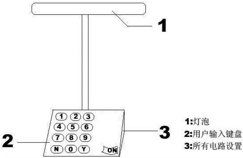
[0020] The main structure of this embodiment includes a light-emitting lamp tube 1, a signal wire 2, a control circuit 3, a curved lampshade 4, a base box 5, a curved and adjustable inner hollow pole 6, a photoreceptor (or light sensor) 7, and a power switch. 8 and the control keyboard 9, one side of the front side of the inclined platform base box 5 is shaped on the control keyboard 9, the upper part of the other side is shaped on the photoreceptor 7, the lower part is shaped on the power switch 8, and the center of the back side of the base box 5 is vertically fixed with a curved Adjustable inner hollow pole 6, the top of the pole is fixed horizontally with an arc lampshade 4, inside the lampshade is a light-emitting lamp tube 1, and inside the arc lampshade 4 is electrically connected through the inner cavity of the pole, and a signal wire 2 is formed. The information is electrically connected with the control circuit 3 installed in the base box 5 to realize the photoelectri...


PUM


Abstract

The invention relates to an illumination device. A main body structure of the illumination device comprises a light emitting lamp tube, a communication guide wire, a control circuit, a chambered lampshade, a base box, a bending adjustable inner hollow supporting rod, a photoreceptor, a light source switch and a control keyboard. The control keyboard is manufactured on one side of the front surface of the turn-table base box, and the photoreceptor is manufactured on the upper part on the other side and the light source switch is manufactured on the lower portion on the other side; the bending adjustable inner hollow supporting rod is fixedly manufactured at the center of the back side of the base box vertically; the chambered lampshade is fixedly manufactured on the top of the supporting rod transversely; the light-emitting lamp tube is manufactured in the lampshade consequently; the communication guide wire which electrically communicates with an inner cavity of the supporting rod is manufactured in the chambered lampshade and electrically communicates with the control circuit in the base box of the device in an information manner, so that photoelectric transmission and dimming automatic control function. The illumination device provided by the invention is simple in circuit principle and safe and reliable in performance, and in particular a table lamp tool formed based on a dimming control circuit has the advantages of being novel in structure, attractive in appearance, convenient to use and operate and the like.

Description

[0001] Technical field: [0002] The invention belongs to the field of lighting equipment, and relates to an energy-saving electronically adjustable lighting device, in particular to a lighting device. [0003] technical background: [0004] There are mainly three types of existing energy-saving lamps with automatic dimming: one is the manual shifting type, which uses buttons to adjust the light intensity through manual control. The existing natural light intensity is effectively used, and the adjustment is not automatic; the second is the touch type, which sends a trigger pulse signal to the touch sensing end through the sensing electrode sheet, and adjusts and controls the light intensity and brightness through manual touch. The light mode is affected by the temperature of the touching hand to a certain extent, and cannot accurately and well meet the needs of dimming. It is often not used in some occasions that have strict requirements on light intensity and brightness, such ...

Claims


Application Information

Patent Timeline
IPC IPC(8): F21S6/00F21V3/02F21V23/02F21V23/04H05B37/02F21Y115/10
CPCF21S6/002F21V3/02F21V23/02F21V23/0464H05B47/11Y02B20/40
Inventor 孙波孙亮
Owner 尤世元
Why Eureka
Try Eureka