Check patentability & draft patents in minutes with Patsnap Eureka AI!

Photo-alignment equipment

A technology of optical alignment and equipment, applied in the field of optical alignment, can solve the problems of increasing equipment cost, increasing the size of the machine and various components, and achieving the effect of increasing equipment cost

Active Publication Date: 2017-05-17
TCL CHINA STAR OPTOELECTRONICS TECH CO LTD
View PDF12 Cites 4 Cited by
  • Summary
  • Abstract
  • Description
  • Claims
  • Application Information

AI Technical Summary

Problems solved by technology

[0006] The invention provides an optical alignment device, which can align the alignment films of different types of liquid crystal display panels without changing the size of each component, so as to solve the need to rotate the substrate before the substrates with different alignment requirements enter the alignment device , when the substrate enters with the long side, it is necessary to increase the size of the machine and each component, thereby increasing the technical problem of equipment cost

Method used


Image

  • Photo-alignment equipment
  • Photo-alignment equipment
  • Photo-alignment equipment

Examples


Embodiment Construction

[0032] The following descriptions of the various embodiments refer to the accompanying drawings to illustrate specific embodiments in which the invention may be practiced. The directional terms mentioned in the present invention, such as [top], [bottom], [front], [back], [left], [right], [inside], [outside], [side], etc., are only for reference The orientation of the attached schema. Therefore, the directional terms used are used to illustrate and understand the present invention, but not to limit the present invention. In the figures, structurally similar elements are denoted by the same reference numerals.

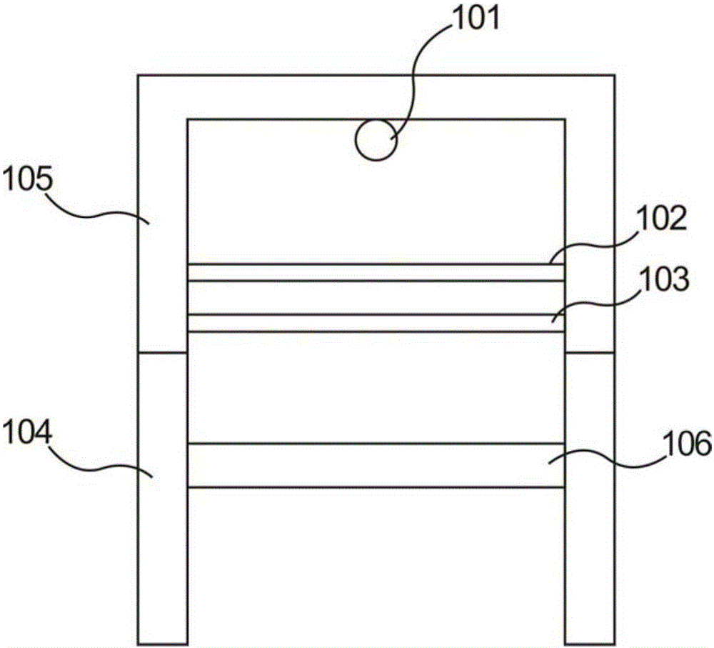
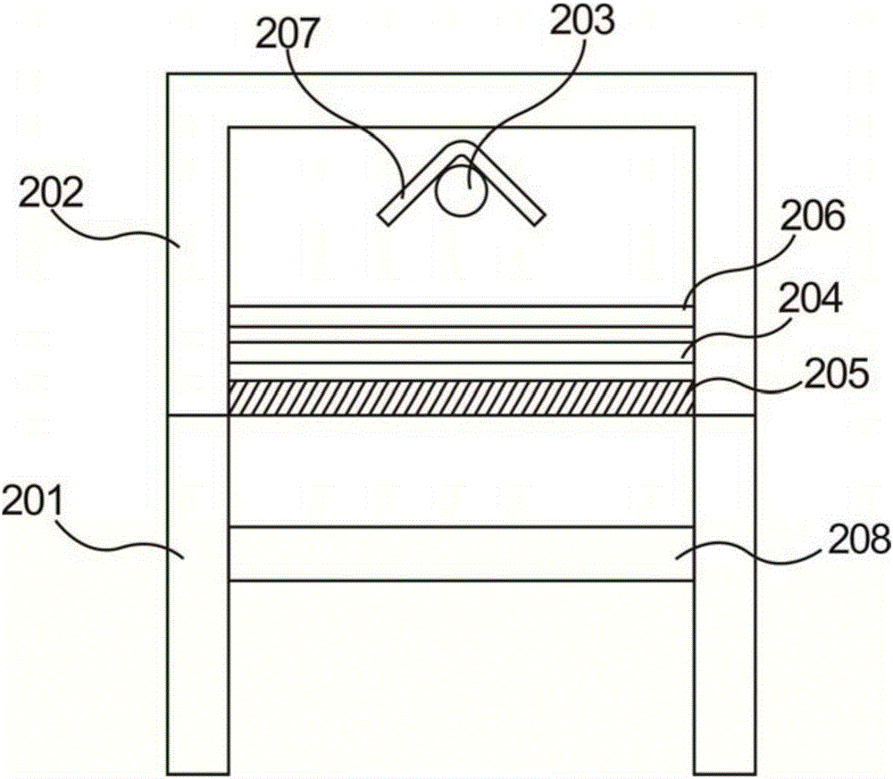
[0033] The present invention is aimed at the existing optical alignment equipment, the compatibility is weak, and the alignment light cannot be adjusted. When the substrates with different alignment requirements enter the equipment, they need to be rotated 90 degrees to enter the long side, so the size of the machine and each component needs to be increased. Satisfying...


PUM


Abstract

The invention provides photo-alignment equipment which comprises a machine used for conveying a to-be-aligned substrate. An alignment light source, polaroid and a twisted nematic liquid crystal box used for adjusting the alignment light polarization direction are arranged above the machine, the photo-alignment equipment has the advantages that compared with existing photo-alignment equipment, the alignment light polarization direction can be adjusted according to the alignment requirement, and therefore alignment films with different alignment requirements can be aligned without rotating the substrate; the technical problems that for the photo-alignment equipment in the prior art, the compatibility is weak, the alignment light cannot be adjusted, when substrates with different alignment requirements enter the equipment, the substrates need to be rotated by 90 degrees to enter the equipment with the long edges, the number of machines and the sizes of all parts need to be increased to meet the light alignment of the substrate, and the equipment cost is increased are solved.

Description

technical field [0001] The invention relates to the technical field of optical alignment of liquid crystal display panels, in particular to an optical alignment device. Background technique [0002] Most of the existing liquid crystal displays are backlight liquid crystal displays, which include a housing, a liquid crystal panel disposed in the housing, and a backlight module disposed in the housing. Generally, a liquid crystal panel is composed of a color filter substrate (Color Filter, CF), a thin film transistor array substrate (Thin Film Transistor Array Substrate, TFT Array Substrate), and a liquid crystal layer (Liquid Crystal Layer) filled between the two substrates. Its working principle is to control the rotation of the liquid crystal molecules in the liquid crystal layer by applying a driving voltage on the CF substrate and the TFT substrate, control the output of light, and refract the light from the backlight module to produce a picture. [0003] In the manufact...

Claims


Application Information

Patent Timeline
Patent Type & Authority Applications(China)
IPC IPC(8): G02F1/1337
CPCG02F1/133788G02F1/1303G02F1/133528G02F1/133711G02F1/133753G02F1/1396
Inventor 赵永超谢忠憬
Owner TCL CHINA STAR OPTOELECTRONICS TECH CO LTD
Features
  • R&D
  • Intellectual Property
  • Life Sciences
  • Materials
  • Tech Scout
  • Unparalleled Data Quality
  • Higher Quality Content
  • 60% Fewer Hallucinations
Learn More