
Camera device resistant to impact and collision

A camera device and impact-resistant technology, which is applied in the field of video surveillance, can solve the problems of not meeting the requirements of cameras, precision equipment, and instruments, the protection device is easily damaged, and the practical application is difficult, so as to achieve stable and reliable assembly and connection, and improve the impact resistance. , Adjust the effect conveniently and quickly

Active Publication Date: 2017-05-17
天芯宜智能网络科技(天津)有限公司
View PDF8 Cites 6 Cited by
  • Summary
  • Abstract
  • Description
  • Claims
  • Application Information

AI Technical Summary

Problems solved by technology

Generally speaking, when the acceleration of this strong impact is greater than 30g, this protective device will be very complicated, accompanied by large volume, difficult installation and debugging, which will bring difficulties to practical application.
When there is a strong impact or collision with a high intensity (greater than 10g) or a large number of times, the existing protective device is easily damaged and cannot meet the requirements of the existing camera, precision equipment, and instrumentation

Method used


Image

  • Camera device resistant to impact and collision
  • Camera device resistant to impact and collision
  • Camera device resistant to impact and collision

Examples


Embodiment Construction

[0023] It should be noted that, in the case of no conflict, the embodiments of the present invention and the features in the embodiments can be combined with each other.

[0024] In describing the present invention, it should be understood that the terms "center", "longitudinal", "transverse", "upper", "lower", "front", "rear", "left", "right", " The orientations or positional relationships indicated by "vertical", "horizontal", "top", "bottom", "inner" and "outer" are based on the orientations or positional relationships shown in the drawings, and are only for the convenience of describing the present invention and Simplified descriptions, rather than indicating or implying that the device or element referred to must have a particular orientation, be constructed and operate in a particular orientation, and thus should not be construed as limiting the invention. In addition, the terms "first", "second", etc. are used for descriptive purposes only, and should not be understood ...


PUM


Abstract

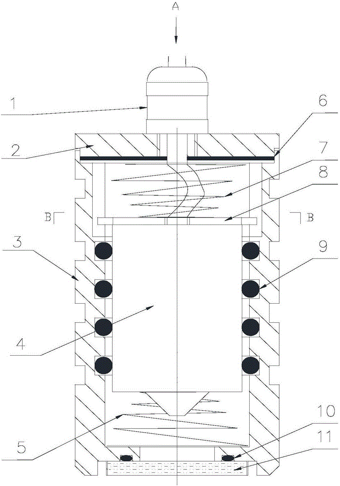
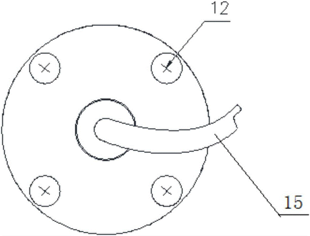
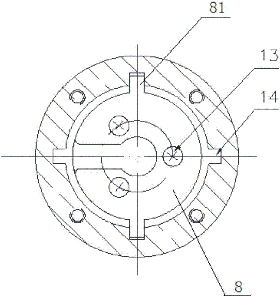
The present invention provides a camera device resistant to impact and collision, belonging to the video monitoring field. The device comprises an impact-resistant body assembly and a collision-resistant body assembly. The impact-resistant body assembly is internally provided with a sealing cavity, and the sealing cavity is internally provided with an impact resistance vibration reduction assembly. The impact resistance vibration reduction assembly comprises elastic elements and a vibration reduction O-shaped circle. The elastic elements are arranged in the sealing cavity and respectively arranged at the upper and lower ends of a camera instrument, the vibration reduction O-shaped circle is arranged at the outer circle of the camera instrument, and the vibration reduction O-shaped circle and the camera are coaxially arranged. The impact-resistant body assembly further comprises a guide plate which is fixed on the camera instrument, circles with guide lug are arranged around the guide plate, the outer edge of the guide lug is arranged at the camera instrument in the protruding mode, a guide slot is arranged at the position of the sealing cavity corresponding to the guide lug, the guide lug is in clearance fit with the guide slot, and the guide lug and the guide slot are slidingly connected up and down. The camera device resistant to impact and collision is resistant to impact and collision, and convenient and rapid to install and debug.

Description

technical field [0001] The invention belongs to the field of video surveillance, and relates to a shock-resistant and collision-resistant camera protection device, which is a camera protection device that can work normally in shock and vibration environments, and is especially suitable for container spreaders under strong shock, collision and vibration conditions. Install camera protection or other precision equipment protection on moving objects. Background technique [0002] Cameras and precision equipment used under conditions of shock, vibration, and collision must be equipped with buffer devices in order to work normally and stably. Generally speaking, when the acceleration of such a strong impact is greater than 30g, the protective device will be very complicated, accompanied by large volume, difficult installation and debugging, which will bring difficulties to practical application. When strong impacts and collisions are strong (greater than 10g) or occur frequently...

Claims


Application Information

Patent Timeline
Patent Type & Authority Applications(China)
IPC IPC(8): G03B17/56H04N5/225
CPCG03B17/56H04N23/50
Inventor 朱小华祖重光周虹伯徐金芬
Owner 天芯宜智能网络科技(天津)有限公司
Learn More