Electrical connector and manufacturing method thereof

A technology of an electrical connector and a manufacturing method, which is applied in the directions of contact manufacturing, connection, and components of a connecting device, etc., can solve the problems of small size of the electrical connector, poor bending and deformation of terminals, and peeling off of the insulating body of the terminal head. Achieve the effect of good overall strength and high yield

Inactive Publication Date: 2017-05-17
苏州优瑞信电子科技有限公司
View PDF7 Cites 7 Cited by
  • Summary
  • Abstract
  • Description
  • Claims
  • Application Information

AI Technical Summary

Problems solved by technology

However, such electrical connectors in the prior art have a large number of terminals, and the overall size of the electrical connector is small, and the thickness of each terminal is very thin, which is prone to bad bending deformation when the terminals are assembled, or the terminal head appears after assembly. Warpage and insulation body peeling, etc., thus affecting product yield

Method used


Image

  • Electrical connector and manufacturing method thereof
  • Electrical connector and manufacturing method thereof
  • Electrical connector and manufacturing method thereof

Examples


Embodiment Construction

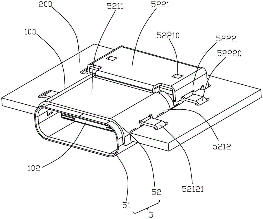
[0032] The present invention will be described in detail below in conjunction with the accompanying drawings. For the convenience of expression, all the directions in this article involving the front and back, up and down, etc. are all in the form of figure 2 The direction is for reference, and the mating end of the electrical connector 100 is regarded as the front end, and the other end thereof is regarded as the rear end.

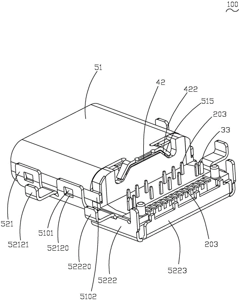
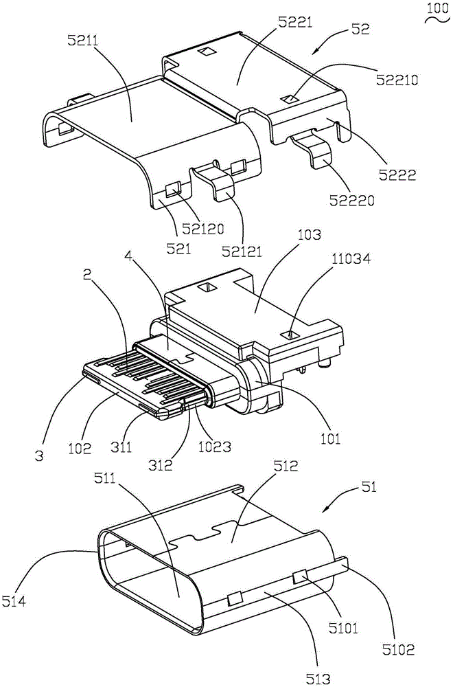
[0033] see Figure 1 to Figure 10 As shown, the present invention discloses an electrical connector 100, which includes an insulating body 1, a terminal 2 and an inner metal part 3 fixed in the insulating body 1, a shielding member 4 and a sleeve set on a part of the outer periphery of the insulating body 1. The metal shell 5 arranged on the periphery of the insulating body 1 . The shielding element 4 is electrically connected to the metal shell 5 . The electrical connector 100 is designed to be fixed on the docking circuit board 200 in a sunken plate...


PUM


Abstract

The invention provides an electrical connector which comprises a first terminal module, a second terminal module, an inner metal part, a third insulator and a metal shell. The first terminal module, the terminal module and the inner metal part are fixed in one body by assembling. The third insulator is arranged at the periphery of the first terminal module, the second terminal module and the inner metal part by integrated molding. The first terminal module comprises a first insulator and a first terminal group including a plurality of first terminals formed in one body through injection molding. The second terminal module comprises a second insulator and a second terminal group including a plurality of second terminals formed in one body through injection molding. At least a part of the front end edge of each of the first terminals is exposed out of the first insulator and at least a part of the front end edge of each of the second terminals is exposed out of the second insulator so as to facilitate the positioning in injection molding. Through three times of injection molding, each terminal and an insulation body are fixed and stable, and the overall strength of the electric connector is good.

Description

technical field [0001] The invention relates to an electrical connector and a manufacturing method thereof. Background technique [0002] For the prior art, please refer to the Chinese utility model patent announcement CN204045770U, which discloses an electrical connector, including an insulating body, a terminal held in the insulating body, a shield, and a metal sleeve set outside the insulating body to form a receiving space. shell. The terminals include an upper row of terminals and a lower row of terminals respectively located on the upper and lower surfaces of the insulating body, and the shielding member is embedded between the upper row of terminals and the lower row of terminals for shielding and grounding. The metal shell includes an inner metal shell set on the periphery of the insulating body and an outer metal shell covering the periphery of the inner metal shell. The insulating body of the electrical connector in the prior art is formed by two injection moldin...

Claims


Application Information

Patent Timeline
Patent Type & Authority Applications(China)
IPC IPC(8): H01R43/16H01R43/20H01R43/24H01R13/02H01R13/405H01R13/504H01R12/72
Inventor 邵兵
Owner 苏州优瑞信电子科技有限公司
Why Eureka
Try Eureka