
Method and device for allocating frequency bands

A technology of frequency band allocation and frequency band, which is applied in the field of frequency band allocation methods and devices, and can solve problems such as low efficiency of frequency band use

Active Publication Date: 2017-05-17
GLOBAL ENERGY INTERCONNECTION RES INST CO LTD +2
View PDF3 Cites 5 Cited by
  • Summary
  • Abstract
  • Description
  • Claims
  • Application Information

AI Technical Summary

Problems solved by technology

[0004] The technical problem to be solved by the present invention is to overcome the defect of low frequency band usage efficiency in the isolation transmission of various services in the existing access network

Method used

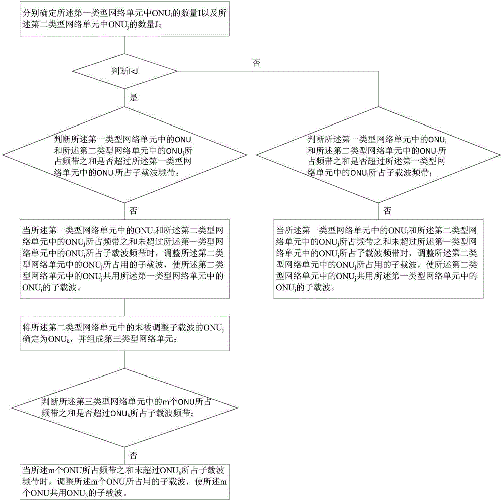

Image

  • Method and device for allocating frequency bands
  • Method and device for allocating frequency bands
  • Method and device for allocating frequency bands

Examples


Embodiment 1

[0050] This embodiment provides a frequency band allocation method.

[0051] First, the frequency spectrum is divided according to network units. For example, the network unit may be an ONU (Optical Network Unit, optical network unit). Different subcarriers are assigned to the multiple ONUs respectively, and the subcarriers may be specific subcarriers for transmission of control information. For the sub-carriers of other data, OFDMA (Orthogonal Frequency Division Multiple Access, Orthogonal Frequency Division Multiple Access) can be used to allocate them to other different ONUs.

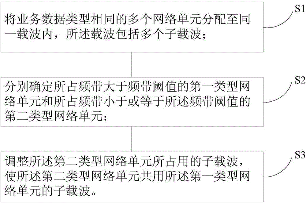
[0052] The flow chart of the method is as figure 1 shown. Including the following steps:

[0053] S1: Allocate multiple network elements of the same service data type into the same carrier, where the carrier includes multiple subcarriers.

[0054] Specifically, multiple network units of the same service data type, such as multiple ONUs, can be allocated to the same carrier through the central op...

Embodiment 2

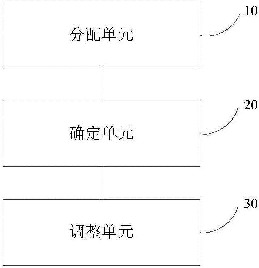
[0103] This embodiment provides a frequency band allocation device, the schematic diagram of which is as follows image 3 As shown, it includes an allocation unit 10 , a determination unit 20 and an adjustment unit 30 .

[0104] First, the frequency spectrum is divided according to network units. For example, the network unit may be an ONU (Optical Network Unit, optical network unit). Different subcarriers are assigned to the multiple ONUs respectively, and the subcarriers may be specific subcarriers for transmission of control information. For the sub-carriers of other data, OFDMA (Orthogonal Frequency Division Multiple Access, Orthogonal Frequency Division Multiple Access) can be used to allocate them to other different ONUs.

[0105] The allocating unit 10 is configured to allocate multiple network elements of the same service data type to the same carrier, where the carrier includes multiple subcarriers.

[0106] Specifically, multiple network units of the same service ...


PUM


Abstract

The invention provides a method and a device for allocating frequency bands. The method includes allocating a plurality of network units with the same types of business data into the same carrier waves comprising a plurality of sub-carrier waves; respectively determining first types of network units with occupied frequency bands larger than frequency band thresholds and second types of network units with occupied frequency bands smaller than or equal to the frequency band thresholds; adjusting the sub-carrier waves occupied by the second types of network units to allow the sub-carrier waves of the first type network units to be shared by the second types of network units. The method and the device have the advantages that distribution of the various sub-carrier waves can be dynamically adjusted in real time, the sub-carrier waves and protective intervals can be allocated, requirements of the different network units on transmission frequency bands can be met, frequency band resources can be utilized to the greatest extent and can be shared without interference on master users, accordingly, the protective intervals can be reduced on the basis of power communication multi-service isolated transmission, the wavelength capacity can be utilized to the greatest extent, and networks can be flexibly and efficiently accessed.

Description

technical field [0001] The present invention relates to the field of communication technology, in particular to a frequency band allocation method and device. Background technique [0002] With the sharp increase in access bandwidth requirements of power terminal communication users, how to further improve the use efficiency of the existing power terminal access network is of great significance. In the access network, TDM-PON, a mechanism that allocates time slices to users on a fixed wavelength, not only greatly limits the available bandwidth of each user, but also wastes the bandwidth of the optical fiber itself. [0003] At present, in the same network carrying multiple communication services, guard intervals are usually used to separate data streams, and most dynamic adjustment schemes are allocated according to different services, which cannot make full use of uplink frequency band resources. Since multiple services are carried on the same network, there is isolation b...

Claims


Application Information

Patent Timeline
IPC IPC(8): H04L5/00H04L12/24H04Q11/00
CPCH04L5/003H04L5/0032H04L5/0044H04L41/0893H04L41/0896H04Q11/0067H04Q2011/0086
Inventor 喻强张浩李炳林黄在朝郭经红吴军民黄辉虞跃刘川姚继明卜宪德吕立冬孙晓艳田文锋
Owner GLOBAL ENERGY INTERCONNECTION RES INST CO LTD
Learn More