
Floating substructure for a wind generator and method of installing same

A technology for wind turbines and infrastructure, applied in the assembly of wind turbines, infrastructure engineering, installation/support configuration of wind turbines, etc., which can solve the problem of low fatigue sensitivity

Inactive Publication Date: 2017-05-17
ESTEYCO ENERGIA +1
View PDF7 Cites 7 Cited by
  • Summary
  • Abstract
  • Description
  • Claims
  • Application Information

AI Technical Summary

Problems solved by technology

With proper design, their fatigue susceptibility is also very low, with service life typically exceeding 50 years

Method used


Image

  • Floating substructure for a wind generator and method of installing same
  • Floating substructure for a wind generator and method of installing same
  • Floating substructure for a wind generator and method of installing same

Examples


Embodiment Construction

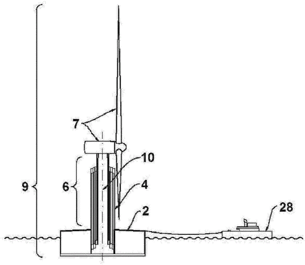
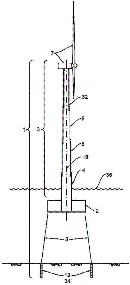
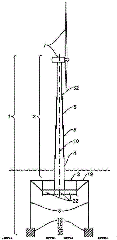
[0107] With reference to the drawings, all the drawings show the floating structure in the installed state. According to the present invention, the floating structure includes: a flotation base 2, which includes at least one body with a substantially hollow shell 25, and the flotation base The maximum horizontal dimension of 2 is greater than the maximum vertical dimension; the building supported by the flotation base 2; the downward pushing device; and at least three fixed cables 8 whose corresponding upper ends are connected to the flotation base 2, And its corresponding lower end is connected to the downward pushing device. In addition, in Figure 1-8 , 10 and Picture 11 In, the building forming part of the floating structure includes the telescopic shaft 3, and the wind turbine device 7 shown therein is optional and / or interchangeable with other accessories, depending on the use of the floating structure. The embodiment of the present invention is described by way of examp...


PUM


Abstract

The invention relates to a floating structure comprising: a flotation base comprising at least one substantially hollow body which can be filled selectively with ballast, the maximum horizontal dimension of the flotation base being greater than the maximum vertical dimension of the flotation base; a construction supported on said flotation base preferably comprising a telescopic tower; downward thrust means; and at least three retaining cables, the upper ends of which are connected to the flotation base, preferably in peripheral positions of the flotation base, and the lower ends of which are connected to the downward thrust means, such that the retaining cables are under tension and apply to the flotation base a downward force which increases the stability of the floating structure. The invention further relates to a method of installing this floating structure.

Description

Technical field [0001] The invention relates to a floating foundation structure for correspondingly installed in water bodies, lakes and other locations and an installation method thereof. [0002] In particular, the base structure of the present invention may be a floating base structure for wind turbines, which is basically made of concrete, which in the installed state includes a semi-outdoor shaft and an underwater flotation base, or open air Shaft and semi-outdoor flotation base. In this document, the term "base structure" refers to the part of the wind tower on which the wind power generation device is supported, and thus includes the tower itself or the shaft. [0003] For the sake of clarity of description, this document generally describes the use of the floating infrastructure of the present invention in the sea, and is not used to limit the scope of the present invention regarding the location of use and the water body. Similarly, for clarity of description, this docume...

Claims


Application Information

Patent Timeline
Patent Type & Authority Applications(China)
IPC IPC(8): B63B35/44F03D80/00
CPCB63B21/50B63B21/502B63B2035/442B63B2035/446E02D5/22F03D13/10F03D13/25F03D13/40F05B2240/9151F05B2240/93Y02B10/30Y02E10/72Y02E10/727B63B77/10F05B2240/95E02D23/02E02D27/425E02D15/08B63B35/44Y02E10/30B63B2209/20F03D80/00B63B21/20B63B21/26B63B2207/02E02B9/08Y02E10/728
Inventor M·A·费尔南怂斯·哥迈斯J·索娜加西亚-康德
Owner ESTEYCO ENERGIA
Learn More