Damper device

A technology of vibration damping device and elastic body, which is applied in the direction of transmission device, fluid transmission device, spring/shock absorber functional characteristics, etc. It can solve the rigidity change of dual-channel shock absorber, the increase of torque converter weight, and the inability to attenuate vibration, etc. question

Active Publication Date: 2017-05-17
AISIN AW CO LTD
View PDF5 Cites 3 Cited by
  • Summary
  • Abstract
  • Description
  • Claims
  • Application Information

AI Technical Summary

Problems solved by technology

However, if the spring constant of the elastic body is to be adjusted to rationalize the natural frequencies of the vibration paths B and C, the overall rigidity of the dual-channel shock absorber will vary greatly
In addition, if the weights of the intermediate flange and the turbine coupled to the intermediate flange are adjusted to rationalize the two natural frequencies, the weight of the flange, the turbine, and the w...

Method used


Image

  • Damper device
  • Damper device
  • Damper device

Examples


Embodiment Construction

[0025] Next, modes for implementing the invention of the present disclosure will be described with reference to the drawings.

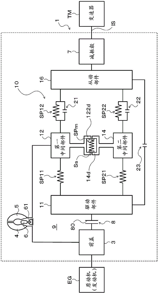
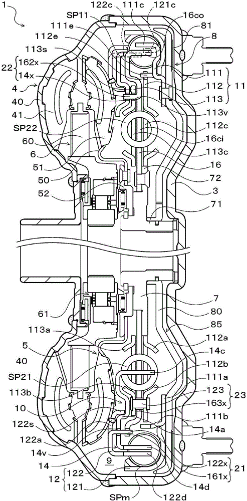
[0026] figure 1 is a schematic configuration diagram showing a starting device 1 including a vibration damping device 10 of the present disclosure, figure 2 It is a sectional view showing the starting device 1 . The starting device 1 shown in these drawings is mounted on a vehicle including an engine (in this embodiment, an internal combustion engine) EG as a prime mover, and includes a front cover connected to a crankshaft of the engine EG in addition to the vibration damper 10. 3. The pump wheel (input side fluid transmission member) 4 fixed to the front cover 3, the turbine wheel (output side fluid transmission member) 5 that can rotate coaxially with the pump wheel 4, is connected to the vibration damping device 10 and fixed to the motor as an automatic A transmission (AT), a continuously variable transmission (CVT), a dual clutch transmission ...


PUM


Abstract

A damper device 10 includes: a drive member 11 to which torque from an engine EG is transmitted; a driven member 16; a first intermediate member 12; a second intermediate member 14; a first outer spring SP11 for transmitting torque between the drive member 11 and the first intermediate member 12; a second outer spring SP12 for transmitting torque between the first intermediate member 12 and the driven member 16; a first inner spring SP21 for transmitting torque between the drive member 11 and the second intermediate member 14; a second inner spring SP22 for transmitting torque between the second intermediate member 14 and the driven member 16; and an intermediate spring SPm for transmitting torque between the first intermediate member 12 and the second intermediate member 14.

Description

technical field [0001] The disclosed invention relates to a vibration damping device having an input member and an output member that transmit torque from an engine. Background technique [0002] Conventionally, as the above-mentioned damping device, a two-channel damper used in connection with a torque converter is known (for example, refer to Patent Document 1). In this damping device, the vibration path from the engine and the lock-up clutch to the output hub is divided into two parallel vibration paths B and C, and the two vibration paths B and C respectively have a pair of springs and are arranged on the Separate middle flange between pair of springs. In addition, in order to make the natural frequencies of the two vibration paths different, the turbine of the torque converter is coupled to the middle flange of the vibration path B, so that the natural frequency of the middle flange of the vibration path B is lower than the natural frequency of the middle flange of the...

Claims


Application Information

Patent Timeline
IPC IPC(8): F16F15/134F16D13/64F16H45/02
CPCF16D13/64F16H45/02F16F15/1236F16F15/13476F16F15/145F16D13/40F16D2300/22F16F15/13492F16F2228/007F16F2228/066F16H2045/0221F16H2045/0294
Inventor 泷川由浩长井大树伊藤和广轮嶋雅树坂本贵生
Owner AISIN AW CO LTD
Why Eureka
Try Eureka