
Imaging method and imaging system

An imaging method and imaging system technology, used in medical science, diagnosis, computer tomography, etc., can solve the problems of non-imaging, deformation of small lesions, and inaccurate quantification.

Active Publication Date: 2017-05-24
SHENYANG INTELLIGENT NEUCLEAR MEDICAL TECH CO LTD
View PDF10 Cites 18 Cited by
  • Summary
  • Abstract
  • Description
  • Claims
  • Application Information

AI Technical Summary

Problems solved by technology

During clinical scanning, since the scanning time of each bed is relatively long (about 2 minutes), the respiratory movement of the subject will have a relatively large impact on the reconstructed image. For example, the movement of the lower part of the lung may cause PET The attenuation coefficient map (μ-Map map) does not match to form banana-shaped artifacts, and small lesions in the moving area are deformed, quantitatively inaccurate or even not visualized

Method used

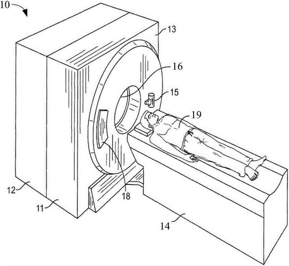
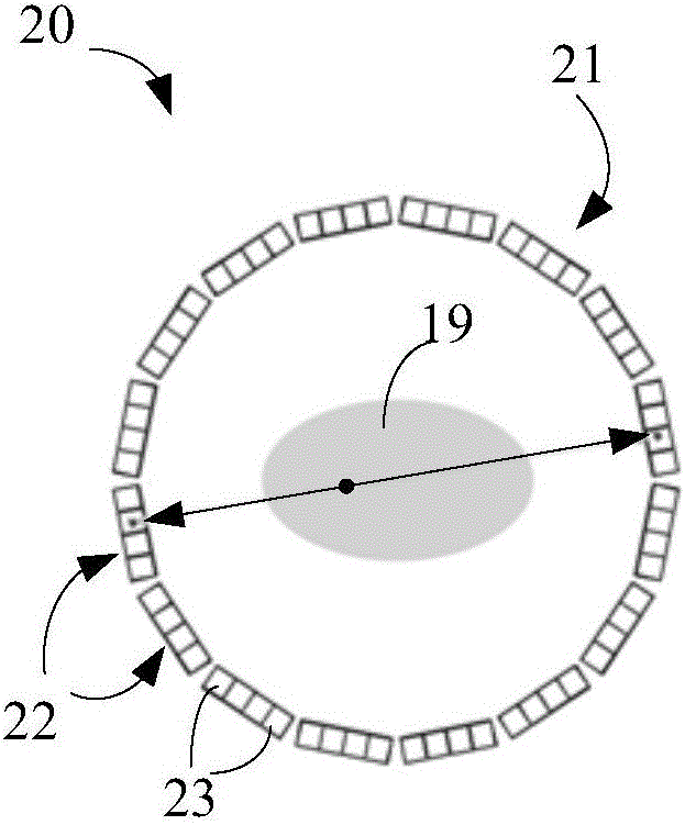
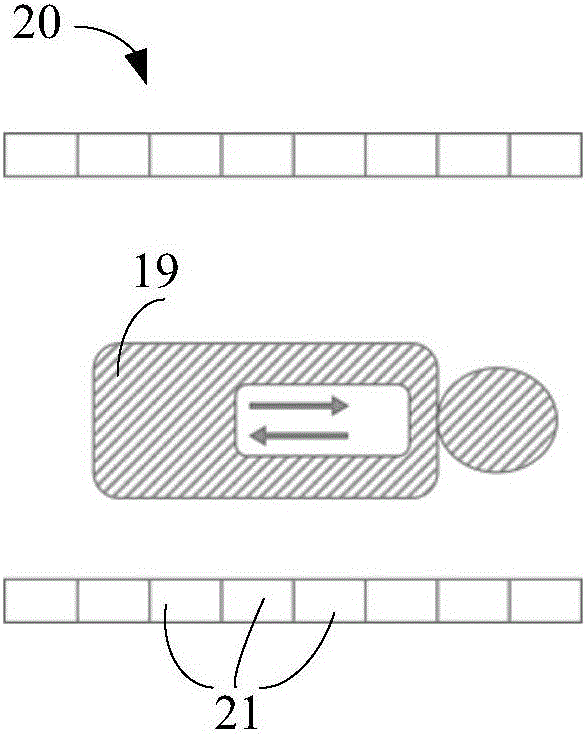

Image

  • Imaging method and imaging system
  • Imaging method and imaging system
  • Imaging method and imaging system

Examples


Embodiment Construction

[0016] Reference will now be made in detail to the exemplary embodiments, examples of which are illustrated in the accompanying drawings. When the following description refers to the accompanying drawings, the same numerals in different drawings refer to the same or similar elements unless otherwise indicated. The implementations described in the following exemplary embodiments do not represent all implementations consistent with this application. Rather, they are merely examples of apparatuses and methods consistent with aspects of the present application as recited in the appended claims.

[0017] The terminology used in this application is for the purpose of describing particular embodiments only, and is not intended to limit the application. Unless otherwise defined, the technical terms or scientific terms used in the present application shall have the common meanings understood by those skilled in the art to which the present invention belongs. "First", "second" and sim...


PUM


Abstract

The invention provides an imaging method. The imaging method comprise: CT picture is obtained by scanning with computer chromatography(CT); PET data is obtained by probing with positron emission chromatography(PET);the PET data is divided into a plurality of PTE data of expected phase position; according to the multiple PET data, unattenuated and uncorrected PED(NAC-PET) picture of corresponding expected phase position is respectively reconstructed; a NAC-PET picture in the multiple NAC-PET pictures of expected phase position, which is mostly matched with the CT picture, is confirmed and become a picture of reference expected phase position; other NAC-PET pictures of expected phase position are confirmed, the deformation field of the picture of reference expected phase position is confirmed; and at least according to the deformation field, the PET data is utilized to reconstructed PET pictures. The invention also discloses a imaging system.

Description

technical field [0001] The present application relates to a medical device, in particular to a multimodal imaging method and system for motion correction. Background technique [0002] Multimodal imaging systems scan using different modalities, such as Computed Tomography (CT) and Positron Emission Computed Tomography (PET). During operation, image quality may be affected by motion, such as respiratory motion, of the subject being imaged. During clinical scanning, since the scanning time of each bed is relatively long (about 2 minutes), the respiratory movement of the subject will have a relatively large impact on the reconstructed image. For example, the movement of the lower part of the lung may cause PET The attenuation coefficient map (μ-Map map) does not match to form banana-shaped artifacts, and small lesions in the moving area are deformed, quantified inaccurately, or even not visualized. Contents of the invention [0003] In view of this, one aspect of the presen...

Claims


Application Information

Patent Timeline
Patent Type & Authority Applications(China)
IPC IPC(8): A61B6/03A61B6/00
CPCA61B6/032A61B6/037A61B6/4411A61B6/4417A61B6/5235
Inventor 孙智鹏刘勺连李明
Owner SHENYANG INTELLIGENT NEUCLEAR MEDICAL TECH CO LTD
Learn More