Contaminated soil in-situ remediation equipment

A technology for in-situ remediation of contaminated soil, applied in the field of remediation of contaminated soil, can solve the problems of not having the function of loosening and breaking soil, and achieve the effect of improving the remediation efficiency and simplifying the remediation process

Inactive Publication Date: 2017-05-24
弘毅天承知识产权股份有限公司
View PDF1 Cites 11 Cited by
  • Summary
  • Abstract
  • Description
  • Claims
  • Application Information

AI Technical Summary

Problems solved by technology

[0004] The object of the present invention is: to solve the problem that the existing soil remediation equipment does not have the function of loosening and breaking soil, the present invention provides a kind of equipment for in-situ repairing of polluted soil, which adds functions of loosening and breaking soil on the basis of the repairing device , Simplify the remediation process of contaminated soil and improve the remediation efficiency

Method used


Image

  • Contaminated soil in-situ remediation equipment

Examples


Embodiment 1

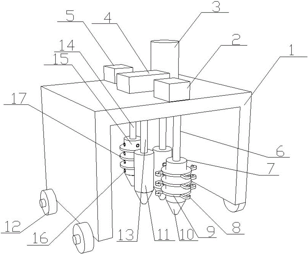
[0019] A device for in-situ restoration of polluted soil, comprising a walking frame 1, on which a rotatable soil loosening bar 7, a soil breaking bar 11 and a soil repairing bar 15 are sequentially arranged, the soil loosening bar 7, soil The broken bar 11 and the soil restoration bar 15 are respectively connected to the top of the walking frame 1 through the first telescopic rod 6, the second telescopic rod 13 and the third telescopic rod 14; rippers 8 are evenly distributed on the outer wall of the soil scarifying rod 7; The soil crushing rods 11 are two and distributed side by side, the soil crushing rods 11 rotate synchronously and in opposite directions, and there is a gap for soil to pass between the soil crushing rods 11; the soil restoration rod 15 and the third telescopic rod 14 are all hollow structures and communicate with each other. The soil repair rod 15 is provided with a chemical spraying hole 16 , and the top of the third telescopic rod 14 communicates with th...

Embodiment 2

[0022] Based on embodiment 1, the bottom of soil loosening rod 7, soil crushing rod 11 and soil repairing rod 15 are all connected with drill bit 10, and drill bit 10 helps to reduce soil loosening rod 7, soil crushing rod 11 and soil repairing rod 15 to enter the soil Resistance, improve work efficiency.

Embodiment 3

[0024] Based on Embodiments 1 and 2, the outer wall of the scarifying rod 7 is provided with a spirally distributed fixing ring 9 , and the scarifying device 8 is located on the fixing ring 9 . By setting the fixed ring 9, the ripper 8 is spirally distributed along the outer wall of the ripper bar 7 to ensure that the ripper 8 can fully excavate the soil during the rotation of the ripper bar 7 .


PUM


Abstract

Provided is contaminated soil in-situ remediation equipment. The contaminated soil in-situ remediation equipment comprises a traveling rack. The traveling rack is sequentially provided with a rotatable soil loosening bar, rotatable soil breaking bars and a rotatable soil remediation bar. The soil loosening bar, the soil breaking bars and the soil remediation bar are connected with the top of the traveling rack through a first telescopic rod, second telescopic rods and a third telescopic rod. Soil scarifiers are evenly distributed on the outer wall of the soil loosening bar. The two soil breaking bars are distributed side by side and are opposite in rotation direction. A gap allowing soil to pass through is reserved between the soil breaking bars. The soil remediation bar and the third telescopic rod are both of a hollow structure and communicate with each other. Chemical spray holes are formed in the soil remediation bar. The top of the third telescopic rod communicates with a chemical tank arranged on the top of the traveling rack. The contaminated soil in-situ remediation equipment can carry out loosening, breaking and remediation of soil simultaneously, the remediation procedures of contaminated soil are simplified, the remediation efficiency of contaminated soil is greatly improved, and the remediation effect is good.

Description

technical field [0001] The invention belongs to the technical field of remediation of polluted soil, and in particular relates to a device for remediating polluted soil in situ. Background technique [0002] As the foundation of human survival, soil is an indispensable material wealth in our life. The utilization and protection of soil resources are closely related to the survival and development of human society. With the continuous acceleration of the industrialization process, the unreasonable exploitation of mineral resources and their smelting discharge, the long-term sewage irrigation and sludge application to the soil, the atmospheric subsidence caused by human activities, and the application of chemical fertilizers and pesticides have caused serious soil pollution. pollute. Soil pollution can directly pollute crops and reduce production, leading to direct economic losses. At the same time, harmful substances can accumulate in crops and enter the human body through t...

Claims


Application Information

Patent Timeline
Patent Type & Authority Applications(China)
IPC IPC(8): B09C1/08B02C18/10
CPCB09C1/08B02C18/10B09C2101/00
Inventor 樊明伟
Owner 弘毅天承知识产权股份有限公司
Why Eureka
Try Eureka