Deburring machine

A deburring machine and frame technology, which is applied to grinding frames, parts of grinding machine tools, machine tools suitable for grinding workpiece edges, etc., can solve the problems of low deburring efficiency of deburring machines, and achieve deburring The effect of high efficiency and low manufacturing cost

Active Publication Date: 2017-05-24
SINPA INDAL AUTOMATION
View PDF5 Cites 4 Cited by
  • Summary
  • Abstract
  • Description
  • Claims
  • Application Information

AI Technical Summary

Problems solved by technology

[0004] The technical problem mainly solved by the present invention is to provide a deburring machine, which can solve the technical problem of low deburring efficiency of the deburring machine in the actual technology

Method used


Image

  • Deburring machine
  • Deburring machine
  • Deburring machine

Examples


Embodiment Construction

[0019] The present invention will be described in detail below in conjunction with the accompanying drawings and embodiments.

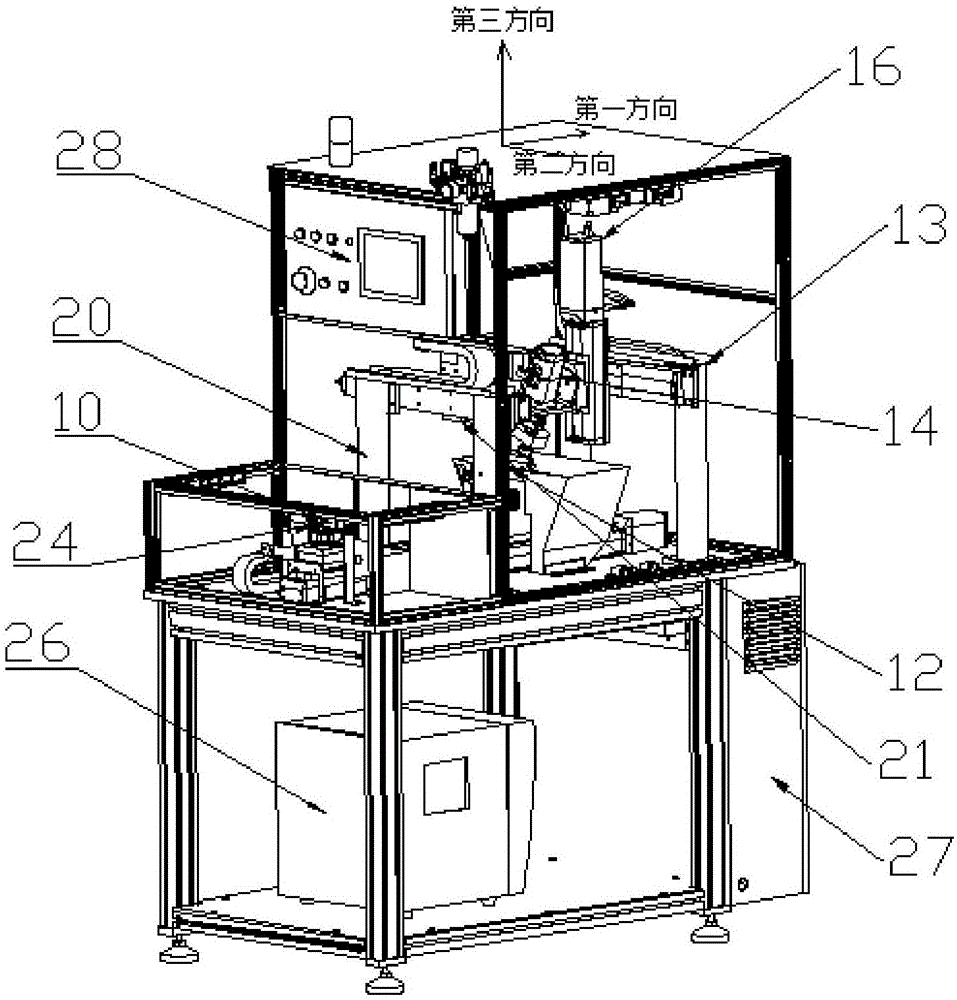
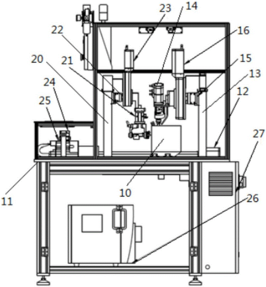
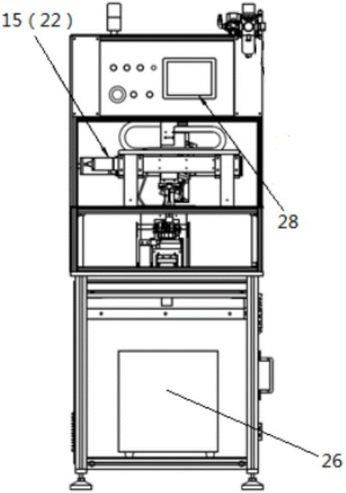
[0020] like Figure 1-Figure 3 as shown, figure 1 It is a schematic diagram of the three-dimensional structure of the deburring machine of the present invention; figure 2 yes figure 1 Schematic diagram of the front view structure of the deburring machine; image 3 yes figure 1 Schematic diagram of the left view structure of the middle deburring machine. The deburring machine includes a frame 11 , a first shaft transmission shaft 12 , a first support frame 13 , a grinding robot 14 , a second transmission shaft 15 , a third transmission shaft 16 , a second support frame 20 and a turning robot 21 .

[0021] The frame 11 is used as the supporting part of the whole deburring machine.

[0022] The first transmission shaft 12 is arranged on the frame 11 and is used to drive the workpiece to move along the first direction. Wherein, the first transmiss...


PUM


Abstract

The invention discloses a deburring machine. The deburring machine comprises a machine frame, a first transmission shaft, a first support, a second transmission shaft and a third transmission shaft. The first transmission shaft is arranged on the machine frame and used for driving a workpiece to move in the first direction; the first support is disposed on the machine frame, and a grinding manipulator is disposed on the first support and used for grinding the workpiece; the second transmission shaft is arranged on the first support, connected with the third transmission shaft and used for driving the third transmission shaft to move in the second direction; the third transmission shaft is disposed on the second transmission shaft, connected with the grinding manipulator and used for driving the grinding manipulator to move in the third direction; the machine frame is further provided with a second support, the second support and the first support are arranged in a spaced mode, and a turnover manipulator is arranged on the second support and used for turning over workpieces. In this way, by means of the deburring machine disclosed by the invention, any position of the to-be-ground surfaces of the workpieces can be ground, the workpieces can be turned over, and omni-directional grinding of the workpieces is achieved.

Description

technical field [0001] The invention relates to the field of mechanical technology, in particular to designing a deburring machine. Background technique [0002] In industrial design, whether it is a metal workpiece or a plastic workpiece, there will be more or less burrs during its production. Although the burrs are small, they directly affect the quality of the product. Therefore, in recent years, with various The industry attaches great importance to deburring. [0003] At present, in order to remove the burrs in the workpiece, a deburring machine is commonly used in the existing field for grinding to remove the burrs. During the deburring process, the deburring machines on the market can only polish the side of the workpiece that needs to be polished. After the side of the workpiece that needs to be polished is polished, the workpiece needs to be taken out, manually turned over the workpiece, and the workpiece is transported again In the process of grinding, human mani...

Claims


Application Information

Patent Timeline
Patent Type & Authority Applications(China)
IPC IPC(8): B24B9/00B24B41/02B24B47/04B24B41/00B24B55/06
CPCB24B9/00B24B41/005B24B41/02B24B47/04B24B55/06
Inventor 孔祥朋汪汐周盖王建伟
Owner SINPA INDAL AUTOMATION
Why Eureka
Try Eureka