Arc edge polishing device and fence shape evaluation method

An arc and edge technology, applied in the field of arc edge grinding device and grid shape evaluation, can solve problems such as difficult to correct shape error, grinding dust flying out, environmental pollution, etc., and achieve high accuracy and high precision. sanding effect

Inactive Publication Date: 2020-10-13
JIANGSU UNIV OF TECH
View PDF7 Cites 1 Cited by
  • Summary
  • Abstract
  • Description
  • Claims
  • Application Information

AI Technical Summary

Problems solved by technology

[0002] Generally, the forming and grinding of large arc chamfers on circular parts belongs to finishing processing, and it is difficult to correct the shape error caused by the rough machining of the previous process of arc chamfering. At present, the method of manual repeated grinding and manual inspection is used to correct large Arc chamfer shape error, due to manual grinding and correction not only requires skilled operators, but sometimes the parts will be scrapped due to grinding force or improper operation, and at the same time, the grinding dust will fly out, causing environmental pollution

Method used


Image

  • Arc edge polishing device and fence shape evaluation method
  • Arc edge polishing device and fence shape evaluation method
  • Arc edge polishing device and fence shape evaluation method

Examples


Embodiment Construction

[0018] The preferred embodiments of the present invention will be described below in conjunction with the accompanying drawings. It should be understood that the preferred embodiments described here are only used to illustrate and explain the present invention, and are not intended to limit the present invention.

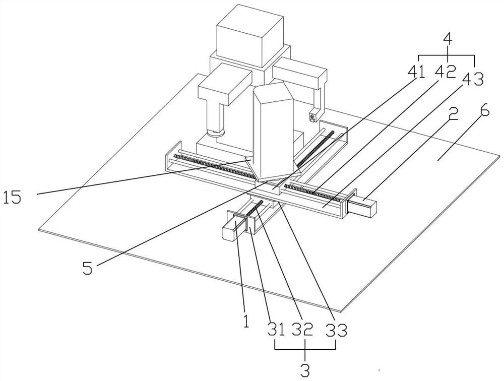
[0019] A circular arc edge grinding device, including a workbench 6, an X-direction screw assembly 3, a Y-direction screw assembly 4, the X-direction screw assembly 3 includes an X-direction screw seat 31, an X-direction screw rod 32, an X-direction screw To the sliding seat 33 and the X-direction drive motor 1, the X-direction screw seat 31 is installed on the workbench 6, and the fuselage of the X-direction drive motor 1 is installed on the X-direction screw seat 31, and the X-direction drive motor 1 The rotating shaft is linked with the X-direction screw rod 32, and the X-direction sliding seat 33 is screwed with the X-direction screw rod 32; the Y-direction screw...


PUM


Abstract

The invention relates to a part polishing technology, in particular to an arc edge polishing device and a fence shape evaluation method. A device conducting cyclic repeated automatic correcting and polishing and automatic detection and evaluating and then conducting correcting and polishing again is adopted, and therefore a new approach is provided for automatic part polishing. The arc edge polishing device comprises a worktable (6), an X-direction screw rod assembly (3) and a Y-direction screw rod assembly (4). The X-direction screw rod assembly (3) comprises an X-direction screw rod seat (31), an X-direction screw rod (32), an X-direction sliding seat (33) and an X-direction drive motor (1). The X-direction screw rod seat (31) is installed on the worktable (6), and a machine body of theX-direction drive motor (1) is installed on the X-direction screw rod seat (31). A rotating shaft of the X-direction drive motor (1) is linked with the X-direction screw rod (32), and the X-directionsliding seat (33) is in screw joint with the X-direction screw rod (32).

Description

technical field [0001] The invention relates to a part grinding technology, in particular to a circular arc edge grinding device and a grid shape evaluation method. Background technique [0002] Generally, the forming and grinding of large arc chamfers on circular parts belongs to finishing processing, and it is difficult to correct the shape error caused by the rough machining of the previous process of arc chamfering. At present, the method of manual repeated grinding and manual inspection is used to correct large Arc chamfering shape error, due to manual grinding and correction not only requires skilled operators, but sometimes the parts will be scrapped due to grinding force or improper operation, and at the same time, due to the flying of grinding dust, it will cause environmental pollution. Contents of the invention [0003] The technical problem to be solved in the present invention overcomes the existing defects, and provides a circular arc edge grinding device and...

Claims


Application Information

Patent Timeline
Patent Type & Authority Applications(China)
IPC IPC(8): B24B9/02B24B49/12B24B47/12B24B1/00B24B47/20
CPCB24B1/00B24B9/02B24B47/12B24B47/20B24B49/12
Inventor 杨龙兴张帅沈光辉杨浩轩蒋新华
Owner JIANGSU UNIV OF TECH
Why Eureka
Try Eureka