High-precision clamper

A clamper and high-precision technology, applied in the direction of workpiece clamping devices, manufacturing tools, etc., can solve problems such as difficult clamping, difficult positioning, and potential safety hazards, and achieve the effects of easy clamping, improved precision, and prevention of offset

Inactive Publication Date: 2017-05-24
黄斌
View PDF4 Cites 3 Cited by
  • Summary
  • Abstract
  • Description
  • Claims
  • Application Information

AI Technical Summary

Problems solved by technology

[0004] Due to the large outer diameter and heavy weight of large-diameter cold-rolled seamless steel pipes, it is not easy to clamp and position, and there are certain safety hazards for workers when testing the quality of the outer surface of steel pipes, so more reliable clamping devices are needed

Method used


Image

  • High-precision clamper

Examples


Embodiment Construction

[0013] In order to make the object, technical solution and advantages of the present invention clearer, the present invention will be further described in detail below in conjunction with the accompanying drawings and embodiments. It should be understood that the specific embodiments described here are only used to explain the present invention, not to limit the present invention.

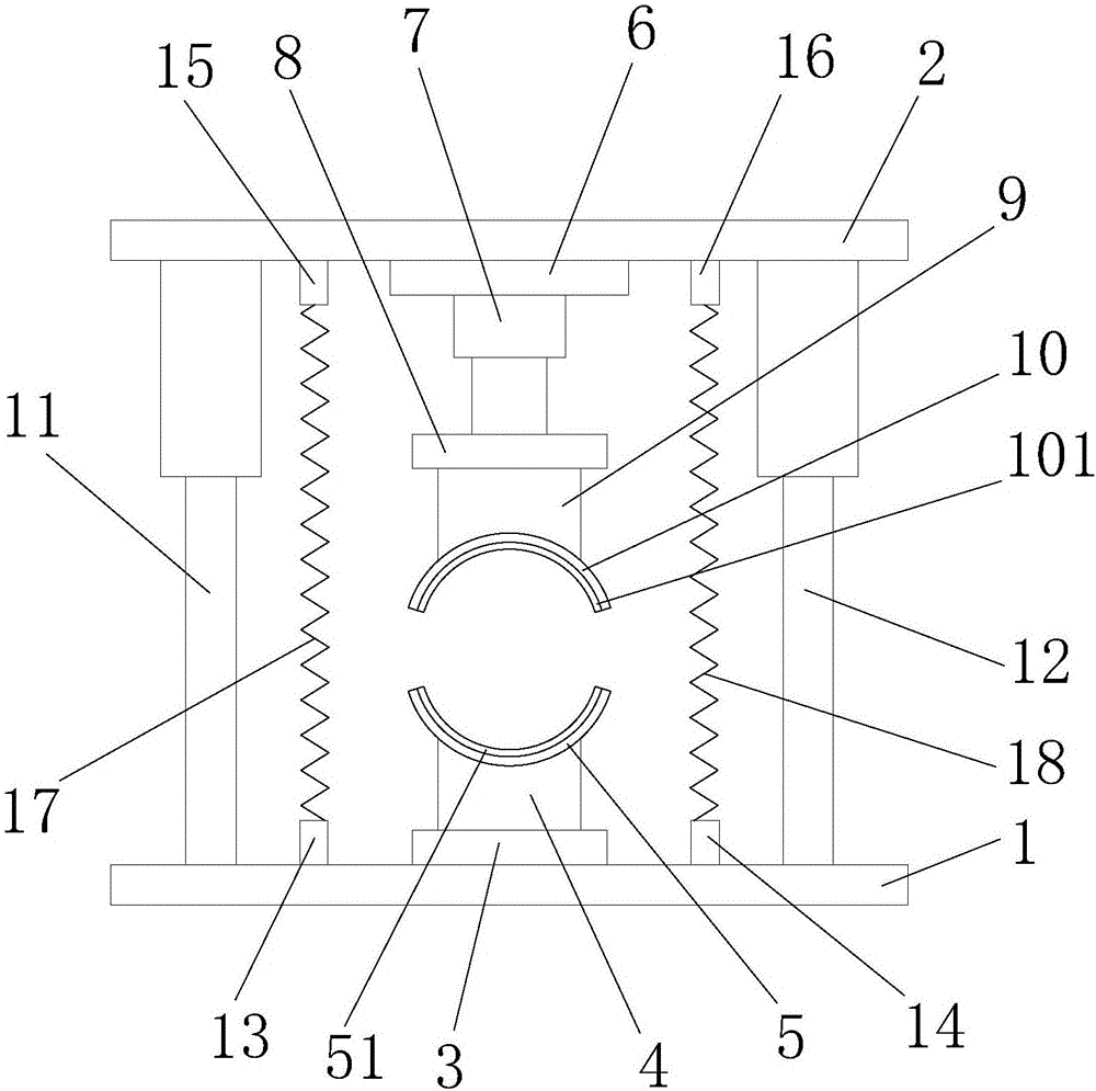
[0014] Such as figure 1 As shown, the clamper with high precision includes a base 1 and a top base 2, a support base 3 is installed on the base 1, and a fixed column A4 is vertically installed on the support base 3. A clamping head A5 is installed on the upper end of the fixed column A4; a cylinder holder 6 is installed on the lower end of the top seat 2, a cylinder 7 is installed on the lower end of the cylinder holder 6, and a support is installed on the lower end of the cylinder rod of the cylinder 7. plate 8, a fixed column B9 is vertically installed at the lower end of the support plate 8, a ...


PUM


Abstract

The invention discloses a high-precision clamper comprising a base and a top seat. A supporting seat is installed on the base. A fixed column A is perpendicularly installed on the supporting seat. A clamping head A is installed at the upper end of the fixed column A. An air cylinder fixing seat is installed at the lower end of the top seat. An air cylinder is installed at the lower end of the air cylinder fixing seat. A supporting plate is installed at the lower end of an air cylinder rod of the air cylinder. The lower end of the supporting seat is perpendicularly provided with a fixed column B. A clamping head B is installed at the lower end of the fixed column B. The clamping head B is located over the clamping head A and identical with the clamping head A in size. A hydraulic cylinder A is installed between the base and the left side of the top seat. A hydraulic cylinder B is installed between the base and the right side of the top seat. The high-precision clamper can conveniently clamp large-diameter steel tubes, follow-up work can be conveniently conducted, and the high-precision clamper is simple in structure, practical and effective and greatly improves the safety of the steel tube during finished product detection.

Description

technical field [0001] The invention relates to the field of clamping technology, in particular to a high-precision clamper. Background technique [0002] The development of steel pipe production technology began with the rise of the bicycle manufacturing industry, the development of petroleum in the early 19th century, the manufacture of ships, boilers, and aircraft during the two world wars, the manufacture of thermal power boilers after the Second World War, the development of the chemical industry and Drilling, production and transportation of oil and natural gas have strongly promoted the development of steel pipe industry in terms of variety, output and quality. The steel pipe is used to transfer fluid and powder, exchange heat and produce mechanical parts and containers, what's more it's a kind of economical steel. Using steel pipes to manufacture building structure grids, pillars and mechanical supports can reduce weight, save metal by 20-40%, and realize factory-li...

Claims


Application Information

Patent Timeline
Patent Type & Authority Applications(China)
IPC IPC(8): B25B11/00
CPCB25B11/00
Inventor 黄斌
Owner 黄斌
Why Eureka
Try Eureka