Capturing device with position compensation and method

A capture device and chassis technology, applied in two-dimensional position/channel control, manufacturing tools, program control manipulators, etc., can solve problems such as difficult to capture targets and difficult optimal landing points, and achieve good anti-interference performance and clear principles , real-time response fast effect

Pending Publication Date: 2017-05-24
CHENGDU EVENTEC SCI & TECH CO LTD
View PDF7 Cites 6 Cited by
  • Summary
  • Abstract
  • Description
  • Claims
  • Application Information

AI Technical Summary

Problems solved by technology

[0003] After the capture device brakes in the landing area, it continues to slide under the action of inertia. It is difficult to accurately brake at the best landing point, and it is even more difficult to capture the target when the inertia is large and the sliding displacement is large.

Method used


Image

  • Capturing device with position compensation and method
  • Capturing device with position compensation and method
  • Capturing device with position compensation and method

Examples


Embodiment 1

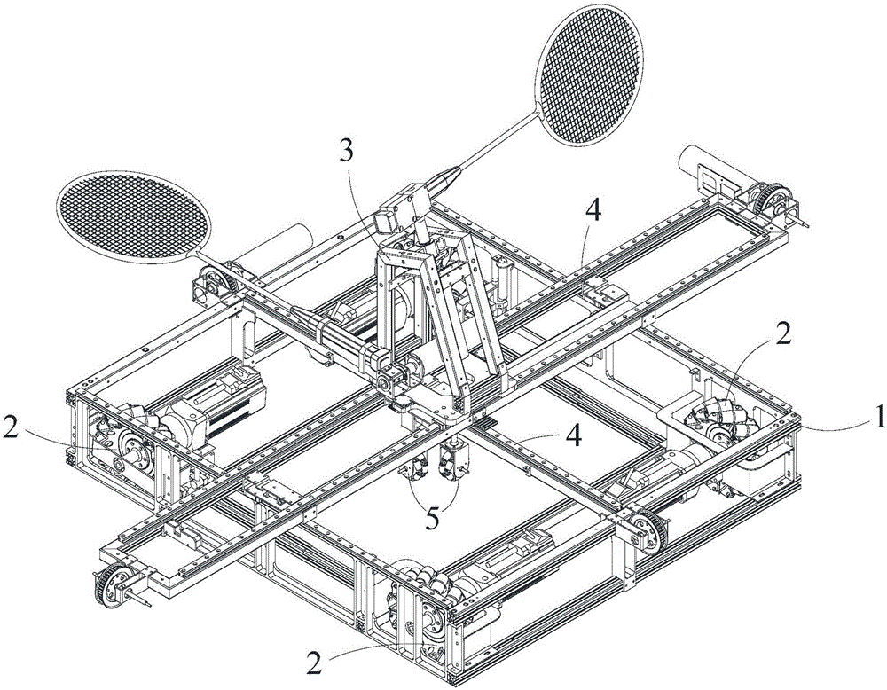
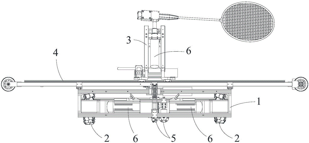
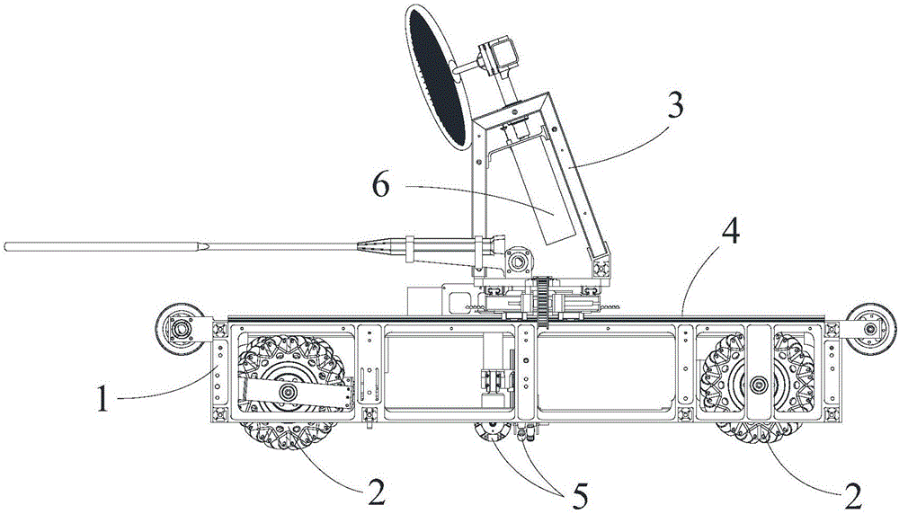
[0067] like Figure 1-8 As shown, a capture device with position compensation according to the present invention includes a drive system, a control system and a chassis 1 provided with at least one traveling wheel 2, and also includes:

[0068] The target mechanism 3 includes a support member 31 on which at least one rotating member 32 is provided, and each rotating member 32 is connected to a badminton racket 33, and the badminton racket 33 rotates relative to the supporting member 31 and uses For hitting badminton, or each rotating part 32 is connected with a tennis racket, and the tennis racket is rotated relative to the supporting part 31 for hitting tennis, or each rotating part 32 is connected with a baseball bat, so The baseball bat rotates relative to the support member 31 for hitting the baseball;

[0069] The moving mechanism 4 is arranged on the chassis 1 and is connected to the target mechanism 3, and the moving mechanism 4 is used to drive the target mechanism 3 ...

Embodiment 2

[0079] like Figure 1-9 As shown, the compensation method of the present invention, using the capture device with position compensation as described in Embodiment 1, includes the following steps:

[0080] A. The control system obtains the landing area of ​​the target in real time, and controls the drive system to drive the chassis 1 to move to the landing area and correct it in real time;

[0081] B. When the chassis 1 moves to the landing point area, all traveling wheels 2 are braked, and the chassis 1 continues to slide under the action of inertia;

[0082] C. The orthogonal omnidirectional wheel component 52 continues to work during the period when the chassis 1 starts to brake all the traveling wheels 2 and inertial moves, so that the motion detection component 51 continues to work in real time, and the motion detection component 51 will detect all the The deviation value between the chassis 1 and the target is fed back to the control system;

[0083] D. The control syst...


PUM


Abstract

The invention discloses a capturing device with position compensation. The capturing device comprises a drive system, a control system and a bottom plate provided with at least one walking wheel. The capturing device further comprises a target mechanism used for intercepting a target, a moving mechanism arranged on the bottom plate and connected with the target mechanism, and a feedback mechanism. The moving mechanism is used for driving the target mechanism to move on the bottom plate. The feedback mechanism is arranged on the bottom plate and comprises a movement detection part and an orthogonal omnidirectional wheel part which is connected with the movement detection part, and the feedback mechanism is used for obtaining the deviation value between the bottom plate and the target and feeding back the deviation value to the control system. By adoption of the device, although the device slides in an inertial manner at the target drop point position, the feedback mechanism records and feeds back the sliding path to the control system, meanwhile, the control system makes the target mechanism move on the bottom plate, the target mechanism is static relative to the drop point, and the target is captured. The capturing device is simple and compact in structure and fast in feedback real-time responding, and the target mechanism can be accurately controlled at the target drop point.

Description

technical field [0001] The present invention relates to the field of electromechanical, in particular to a capture device and method with position compensation. Background technique [0002] For the capture of moving targets falling in the air, due to the comprehensive influence of various factors during the falling process of the target, it is necessary to track and locate the target in real time, determine the landing area of ​​the target, and the capture device quickly approaches the landing area in a very short time. The trajectory and the real-time corrected landing area correct the movement path of the capture device itself in real time, and finally capture the target in the landing area. [0003] After the capture device brakes in the landing area, it continues to slide under the action of inertia. It is difficult to accurately brake at the optimal landing point, and it is even more difficult to capture the target when the inertia is large and the sliding displacement...

Claims


Application Information

Patent Timeline
Patent Type & Authority Applications(China)
IPC IPC(8): B25J5/00B25J9/16A63B69/00G05D1/02
CPCA63B69/0002A63B69/0017A63B69/38G05D1/02B25J5/007B25J9/1679
Inventor 黄山伍功宇王钐菖董继波江山
Owner CHENGDU EVENTEC SCI & TECH CO LTD
Why Eureka
Try Eureka