3D printing head with air inlet device and cooling method of printing head

A technology of air inlet device and print head, which is applied in the direction of coating device, 3D object support structure, manufacturing tools, etc. It can solve the problems of easy breakage, incomplete curing, and insufficient structural strength of the product, and achieve the effect of ensuring printing quality

Inactive Publication Date: 2017-05-24
DONGGUAN RUIDI THREE DIMENSIONAL ELECTRONICS TECH
View PDF6 Cites 18 Cited by
  • Summary
  • Abstract
  • Description
  • Claims
  • Application Information

AI Technical Summary

Problems solved by technology

If the material solidifies too fast, when the second layer of spray material is printed, the first layer of spray material has been completely cured, which will cause the two layers of material to not fully cure into a whole, which will lead to the final formed product Insufficient structural strength, easy to break

Method used


Image

  • 3D printing head with air inlet device and cooling method of printing head
  • 3D printing head with air inlet device and cooling method of printing head
  • 3D printing head with air inlet device and cooling method of printing head

Examples


Embodiment Construction

[0038] The present invention will be further described below in conjunction with specific embodiments and accompanying drawings.

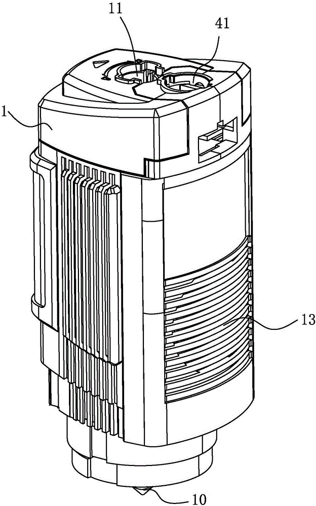
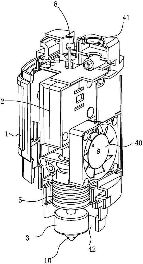
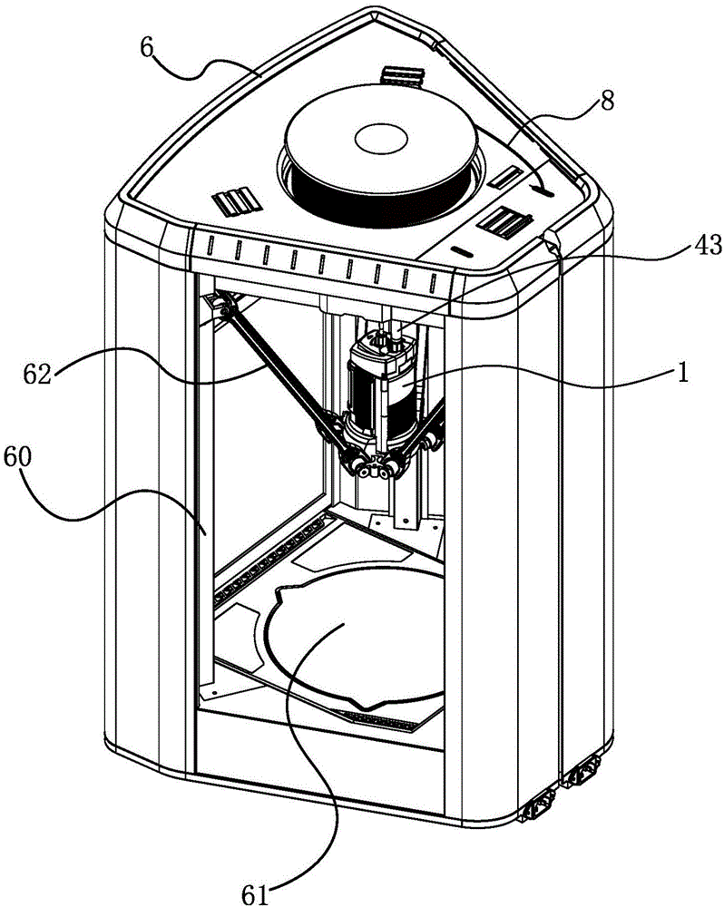
[0039]See figure 1 , 2 , 3, and 4, this is the first embodiment of the present invention, which is a 3D printing head with an air inlet device, the printing head is installed in the printer body 6, a cavity 60 is formed in the printer body 6, and the printing The head works in the cavity 60 . The print head is driven by the mechanical arm 62, which can realize the operation in the X / Y / Z direction. The mechanical arm 62 has been recorded in many patent documents as a mature technology. , US20120171383 A1, and US patent documents of 20130049261A1, all of which propose related technical solutions based on this mechanical arm. This kind of mechanical arm has the advantages of high speed and high precision compared with the general horizontal three-dimensional mechanical arm.

[0040] A printing platform 61 is installed below the cavity 60, and the ...


PUM


Abstract

The invention provides a 3D printing head with an air inlet device and a cooling method of the printing head. The printing head comprises a shell and a heating assembly installed in the shell. A printing raw material enters the shell, then is heated and melted by the heating assembly and is discharged through a jet nozzle of the printing head, and printing operation is conducted. The printing head further comprises the air inlet device. The air inlet device comprises an air inlet formed in the upper portion of the shell and an air outlet formed in the lower portion of the shell. Outside cold air enters the shell through the air inlet, passes through the heating assembly and is exhausted through the air outlet. The 3D printing head with the air inlet device and the cooling method of the printing head have the following effects that for a conventional printing head, heat dissipation can be conducted on the printing head in time; and for products low in melting point and curing speed, the 3D printing head can directly accelerate the curing and stabilizing effects of the printing material, and accordingly the products in more complex shapes can be manufactured. In addition, the outside gas introduced through the air inlet device can serve as inert gas so that the raw material discharged by the jet nozzle of the printing head can be protected.

Description

[0001] Technical field: [0002] The invention relates to the technical field of 3D printer products, in particular to a 3D printing head with an air inlet device and a cooling method for the printing head. [0003] Background technique: [0004] 3D printers have developed rapidly in the past few years. The existing 3D printers first need to use a computer to model before working, and then perform layered "slicing" of the built 3D model, and then "print" layer by layer from bottom to top. ” Each layer is sliced, resulting in a 3D product identical to the model built. [0005] This kind of 3D printer is also called hot-melt material spray printing. Its working principle is similar to that of traditional inkjet printers. The difference is that the "ink" used by this 3D printer is a kind of hot-melt material, such as hot-melt wax , Hot melt adhesive. The molten hot-melt material is sprayed on the printing platform by the printing mechanism, and "printing" is performed layer by l...

Claims


Application Information

Patent Timeline
Patent Type & Authority Applications(China)
IPC IPC(8): B29C64/118B29C64/209B33Y30/00
CPCB33Y30/00
Inventor 赵舜培陈远荣
Owner DONGGUAN RUIDI THREE DIMENSIONAL ELECTRONICS TECH
Why Eureka
Try Eureka