A stamping device for a punching machine

A stamping device and technology of a punching machine, which is applied in the field of stamping devices of a punching machine, can solve the problems of reduced precision of the punching machine, increased friction of the crankshaft mechanism, and wear, and achieve the effects of smooth operation of the crankshaft mechanism, reduced use requirements, and high service life

Active Publication Date: 2018-11-30
宁波澳玛特高精冲压机床股份有限公司
View PDF1 Cites 0 Cited by
  • Summary
  • Abstract
  • Description
  • Claims
  • Application Information

AI Technical Summary

Problems solved by technology

Existing punching machines generally use the motor to directly drive the crankshaft to rotate, and then the crankshaft pushes the punch to stamp the mold. Due to the large resistance encountered during the stamping process, this kind of slow operation requires high-strength output. The power has high requirements on the motor. It is difficult to guarantee the stability of the motor during operation, and it is easy to shake. Once the motor shakes, the crankshaft will also shake to a certain extent, which will lead to a decrease in the precision of stamping.
On the other hand, the friction of the crankshaft mechanism in the stamping device increases during transmission, and the wear is serious. After the wear, the precision of the punching machine is also reduced, and the overall life of the punching machine will also be greatly reduced.
For example, the patent application No. 201310033319.X is a patent for a punch press, which uses an ordinary crankshaft mechanism on the stamping device of the punch press. Although a counterweight mechanism is added to balance the force of the punch press, it still cannot solve the problem of the punch press. Movement is a matter of wear inside the crank mechanism

Method used


Image

  • A stamping device for a punching machine
  • A stamping device for a punching machine
  • A stamping device for a punching machine

Examples


Embodiment Construction

[0026] The following are specific embodiments of the present invention and in conjunction with the accompanying drawings, the technical solutions of the present invention are further described, but the present invention is not limited to these embodiments.

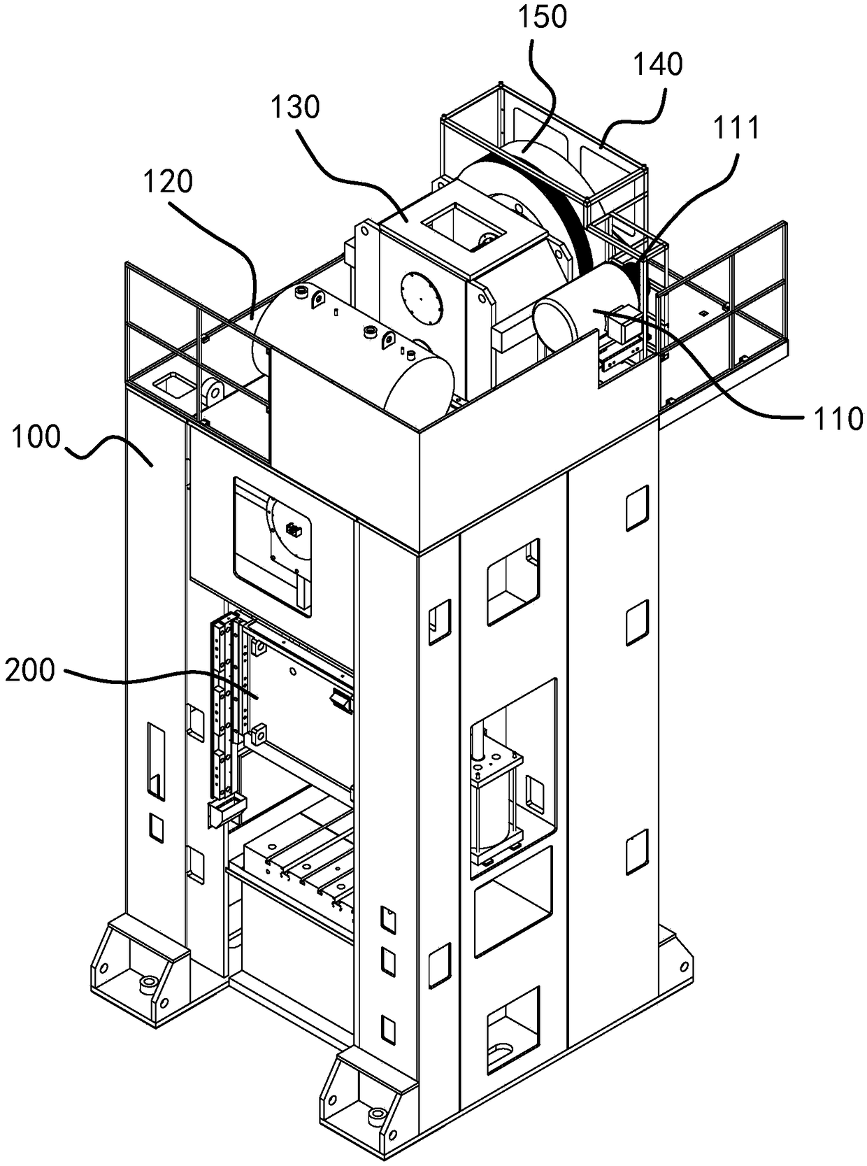
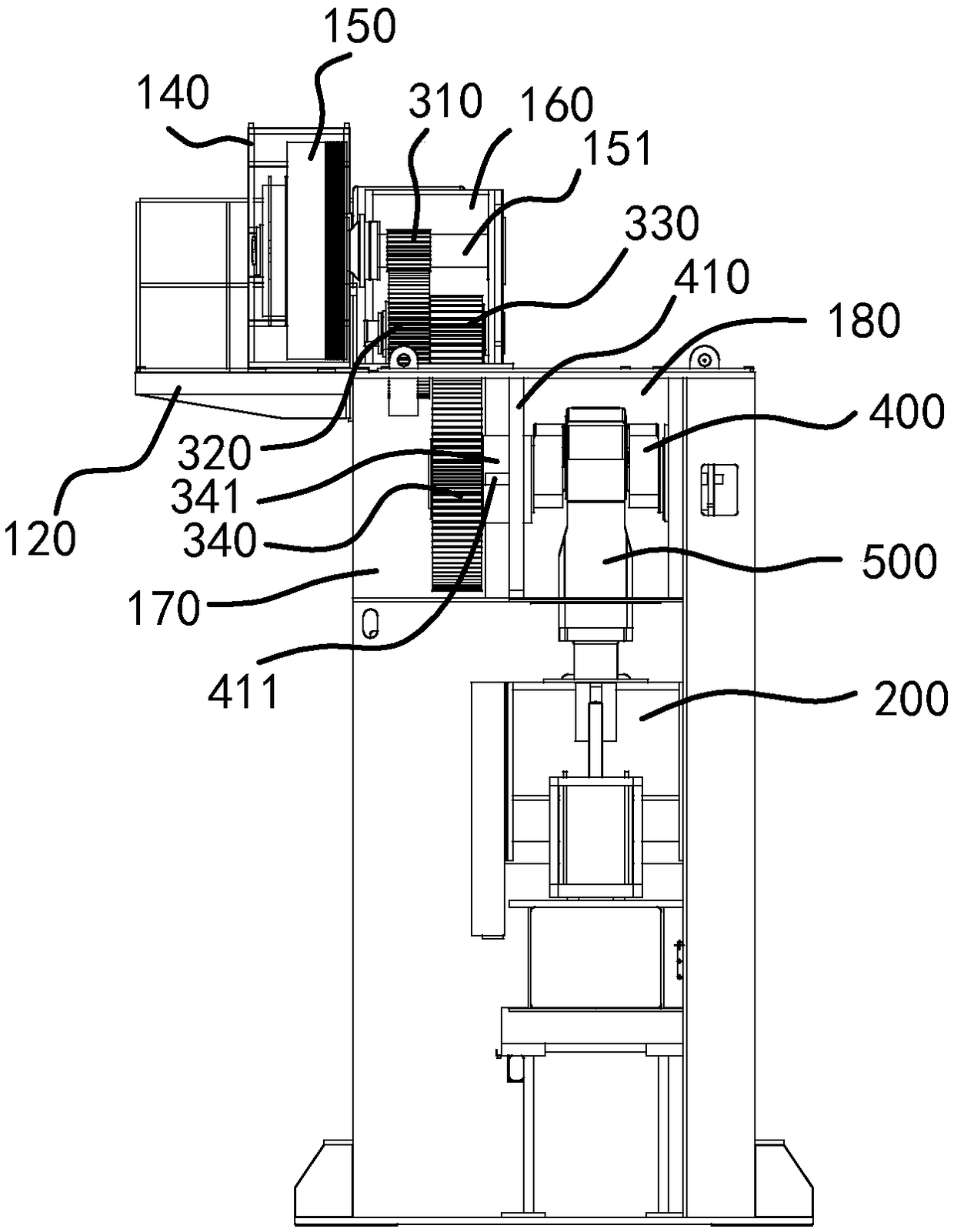
[0027] Such as figure 1 and figure 2 As shown, the present invention provides a stamping device for a punch press, including a mounting frame 100, the mounting plate 120 is provided on the mounting frame 100, and a first mounting position 160 is provided on the upper end surface of the mounting plate 120. The second installation position 170 and the third installation position 180 are provided on the lower end surface of the installation plate 120, and the second installation position 170 and the third installation position 180 are separated by a partition 410; the motor 110 is arranged on the first installation position 160 On the side, the motor 110 has a power shaft, and the power shaft is sleeved with a runner 111; t...


PUM


Abstract

The invention provides a punching device for a punching machine, and belongs to the technical field of machines. The punching device solves the technical problems that an existing punching structure of a punching machine is poor in structure stability and large in abrasion. The punching device comprises an installation support, a motor, a retarding mechanism, a crankshaft and a connecting rod; the installation support is provided with an installation plate, a first installation position is arranged on the upper end face of the installation plate, a second installation position and a third installation position are arranged on the lower end face of the installation plate; the motor is arranged on the side portion of the first installation position and is provided with a power shaft, and a rotary wheel is connected to the power shaft in a sleeving manner; the retarding mechanism comprises a flywheel and multiple stages of reduction gears, the multiple stages of reduction gears are arranged in the first installation position and the second installation position correspondingly, and the flywheel is in transmission connection with the rotary wheel and is in transmission connection with the multiple stages of reduction gears; the crankshaft is arranged in the third installation position and is in transmission connection with the multiple stages of reduction gears; and the connecting rod is arranged on a crank throw of the crankshaft, and a punching pin is connected to the lower end of the connecting rod. The punching device has the beneficial effects of being high in stability and small in abrasion.

Description

technical field [0001] The invention belongs to the technical field of mechanical machine tools, and in particular relates to a punching device for a punching machine. Background technique [0002] The punch press is a stamping press machine made of integrated special cast iron alloy processing, which has high rigidity, shock resistance and high precision. The punching machine often needs to slow down in the process of pressing down the punch, especially in the process of pressing down after the punch is in contact with the mold. The slow speed can ensure that the force of the punch is balanced during the stamping process, and the stamping effect is good. Existing punching machines generally use the motor to directly drive the crankshaft to rotate, and then the crankshaft pushes the punch to stamp the mold. Due to the large resistance encountered during the stamping process, this kind of slow operation requires high-strength output. The power has high requirements on the mo...

Claims


Application Information

Patent Timeline
Patent Type & Authority Patents(China)
IPC IPC(8): B30B1/26B30B15/00
CPCB30B1/266B30B15/0088
Inventor 余志锋吕刚缪斌斌
Owner 宁波澳玛特高精冲压机床股份有限公司
Why Eureka
Try Eureka