
Movable storage rack for oxygen cylinder

An oxygen cylinder and mobile technology, applied in the field of movable racks, can solve the problems of inability to move at will, messy storage, inconvenient handling, etc., and achieve the effects of saving labor, large market competitiveness, and energy saving.

Inactive Publication Date: 2017-05-24
梁斌
View PDF9 Cites 12 Cited by
  • Summary
  • Abstract
  • Description
  • Claims
  • Application Information

AI Technical Summary

Problems solved by technology

[0002] Oxygen cutting is often used in engineering construction. Usually, the oxygen cylinders used are casually placed together, causing messy storage and inconvenient handling, which causes a large degree of safety hazards.
Although there will also be a kind of oxygen cylinder placement frame on some sites, the frame body is surrounded by a simple bottom plate and the columns arranged on the four corners of the bottom plate, and there is also a reinforcement between two adjacent columns to limit the escape of the oxygen cylinder. Beams and oxygen cylinders can be placed in the rack in a centralized and orderly manner to avoid potential safety hazards caused by the dumping and impact of the oxygen cylinder. The movable rack is transferred, but the existing racks encounter many problems in the process of use. Sometimes they need to be moved by manpower during the transfer, which is very laborious, and it also requires a lot of strength when moving away from the rack. It is very troublesome, and the function is relatively single. Therefore, we propose a movable oxygen bottle storage rack

Method used


Image

  • Movable storage rack for oxygen cylinder
  • Movable storage rack for oxygen cylinder
  • Movable storage rack for oxygen cylinder

Examples


Embodiment Construction

[0016] The following will clearly and completely describe the technical solutions in the embodiments of the present invention with reference to the accompanying drawings in the embodiments of the present invention. Obviously, the described embodiments are only some, not all, embodiments of the present invention.

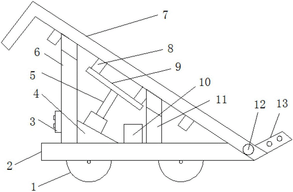
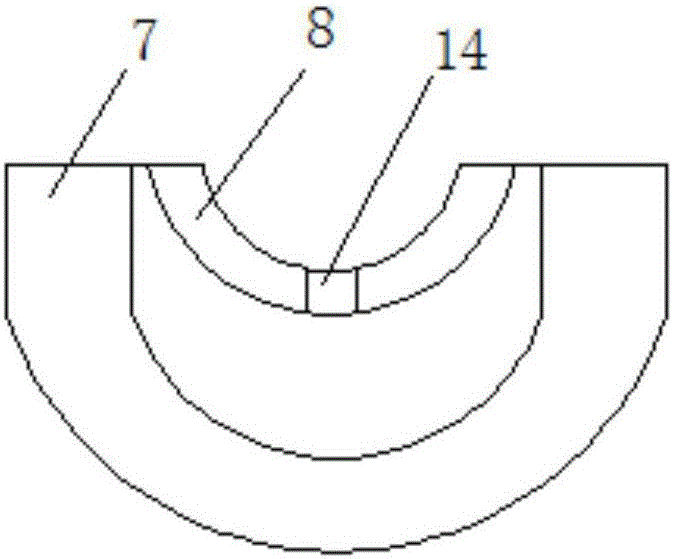
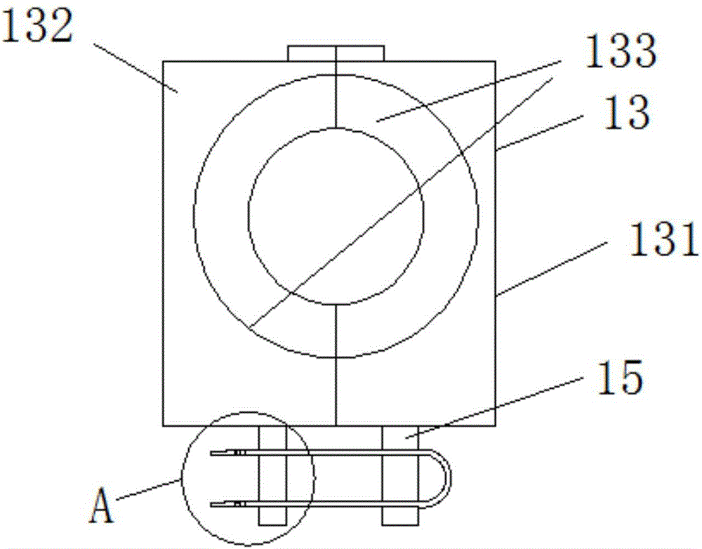
[0017] refer to Figure 1-4 , a movable rack for oxygen cylinders, comprising a base 2, the bottom of the base 2 is provided with a roller 1, the left and right sides of the upper end of the base 2 are respectively provided with a first pole 6 and a second pole 11, the first pole A PLC controller 3 is installed on the rod 6, and the upper ends of the first pole 6 and the second pole 11 form an arc groove, and the right side of the base 2 is movably connected with an oxygen cylinder frame 7 through a first pin shaft 12, and the oxygen cylinder The lower end of the bottle holder body 7 is equidistantly provided with arc-shaped plates 8, and the surface of the arc-shape...


PUM


Abstract

The invention relates to the technical field of movable storage racks, in particular to a movable storage rack for an oxygen cylinder. The movable storage rack comprises a base, rolling wheels are arranged at the bottom end of the base, a supporting device is connected to one end, close to a first pin shaft, of an oxygen cylinder frame body, and a right-angle fixing block is arranged on one side, close to a first supporting rod, of the upper end of the base; the slope surface of the right-angle fixing block is parallel to the oxygen cylinder frame body, and the right-angle fixing block is provided with an electric telescopic column; a push plate is connected to the side, away from the right-angle fixing block, of the electric telescopic column, and the push plate is fixedly connected with an arc-shaped plate corresponding to the push plate in position; and a power supply is arranged on the side, close to a second supporting rod, of the upper end of the base, and the power supply, the electric telescopic column and a PLC are electrically connected. The movable storage rack has large market competitiveness, and compared with an existing movable storage rack, more functions are achieved, the singular problem is avoided, and later popularization is facilitated.

Description

technical field [0001] The invention relates to the technical field of movable racks, in particular to a movable rack for oxygen cylinders. Background technique [0002] Oxygen cutting is often used in engineering construction. Usually, the oxygen cylinders used are randomly thrown together, which is messy and inconvenient to carry, which causes a large degree of safety hazards. Although there will also be a kind of oxygen cylinder placement frame on some sites, the frame body is surrounded by a simple bottom plate and the columns arranged on the four corners of the bottom plate, and there is also a reinforcement between two adjacent columns to limit the escape of the oxygen cylinder. Beams and oxygen cylinders can be placed in the rack in a centralized and orderly manner to avoid potential safety hazards caused by the dumping and impact of the oxygen cylinder. The movable rack is transferred, but the existing racks encounter many problems in the process of use. Sometimes t...

Claims


Application Information

Patent Timeline
IPC IPC(8): B62B3/10
CPCB62B3/104B62B2202/022
Inventor 梁斌
Owner 梁斌
Learn More